Fuel tank inlet device

A technology of injection device and fuel tank, which is applied in the direction of power unit, transportation and packaging, and the arrangement combined with the fuel supply of internal combustion engines, etc., can solve problems such as backflow, and achieve the effect of preventing fuel theft

Inactive Publication Date: 2008-04-02
TRUCKPROTECT
View PDF0 Cites 3 Cited by
  • Summary
  • Abstract
  • Description
  • Claims
  • Application Information

AI Technical Summary

Problems solved by technology

[0004] These devices still have the problem of reflow, at least when injecting at high speed
In addition, the above devices present other assembly and safety issues

Method used


Image

  • Fuel tank inlet device
  • Fuel tank inlet device
  • Fuel tank inlet device

Examples


Embodiment Construction

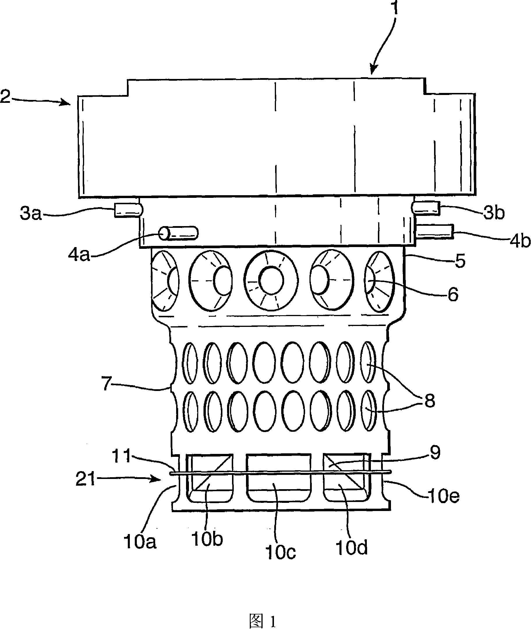
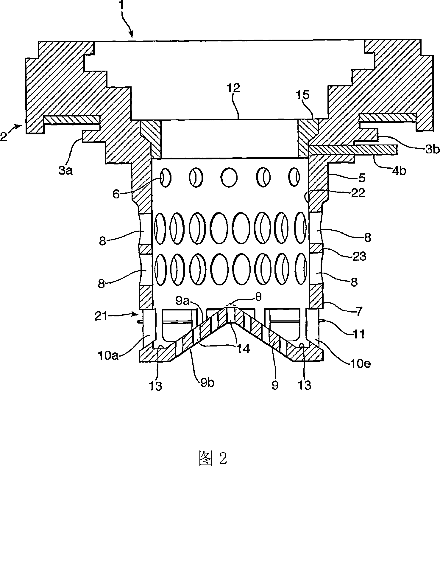
[0085]1 and 2 are a side view and a schematic cross-sectional view, respectively, of a fuel tank filling device in a preferred embodiment of the present invention in which the inner surface of the end portion has a conical portion to direct fuel flow towards the side wall. The fuel tank filling device is marked 1 in the figure, and it can prevent the liquid fuel in the fuel tank equipped with the device from being stolen. The device 1 contains an attachment 2 which enables the device 1 to be securely connected to a fuel tank or a filler neck; a fuel injection body 5 for receiving fuel, which contains an injection port 12 for injecting fuel , also contains an output port to output fuel to the fuel tank. The fuel injection body 5 also has a side wall 7 extending from a first end of the device near or within the filler opening 12 to a further end portion 9 connected to a second end portion of the device 1 . The end portion 9 has an inner surface 9a for receiving fuel from the fu...


PUM


Abstract

An inlet device (1) for a tank, the device comprising an attachment portion (2) adapted to allow the device to be secured to a tank or filler neck thereof and an inlet body portion (5) for the receipt of liquid, the inlet body portion comprising an inlet (12) for the ingress of liquid and an outlet for the egress of liquid into a tank, the inlet body portion comprising a wall portion (7) depending from a first end of the device at or in the vicinity of the inlet to an end portion (9) associated with a second end of the device, the end portion having an inner surface (9a) for the receipt of liquid and an outer surface (9b), the outlet being provided by a plurality of bores (10a-e) in a part (21) of the wall portion associated with the end portion and the inner surface of the end portion being shaped so as to direct liquid towards one or more of said bores, the inner surface of the end portion being provided with a surface of revolution for directing liquid towards one or more of said bores, one or more of said bores extending from a bore inlet (18) for the receipt of liquid to a bore outlet (19) for the egress of liquid, wherein the bore outlet has a greater cross-sectional area than the corresponding bore inlet.

Description

technical field [0001] The invention relates to a fuel tank filling device, especially a fuel tank filling device which can prevent fuel from being stolen from the fuel tank. Background technique [0002] The fuel tank filling device is used to prevent theft of fuel in the fuel tank. Many of these devices consist of an accessory that securely attaches the device to the fuel tank, and a body that receives the fuel injection and that, in use, protrudes into the fuel tank (typically the fuel tank of a vehicle). The body shall be of sufficient size to accommodate the fuel transfer system. The body typically has holes through which fuel flows into the tank. The holes in the body are sufficiently small to prevent the fuel in the tank from being sucked out of the tank through a hose or similar device. This type of device is generally prone to reverse flow. When the transmission speed of fuel into the fuel tank through the small hole is not enough, it will form a back pressure to...

Claims


Application Information

Patent Timeline
IPC IPC(8): B60K15/04
CPCB60K15/0403
Inventor 理查德·奈杰尔·福勒
Owner TRUCKPROTECT
Why Eureka
Try Eureka