Anti-theft fuel tank of locomotive

A fuel tank and locomotive technology, which is applied to locomotives and other directions, can solve the problems of no anti-theft oil device and fuel theft, etc., and achieve the effects of preventing locomotive fuel from being stolen, reducing economic losses, and having a simple structure.

Inactive Publication Date: 2015-11-04
CRRC ZIYANG CO LTD
View PDF8 Cites 0 Cited by
  • Summary
  • Abstract
  • Description
  • Claims
  • Application Information

AI Technical Summary

Problems solved by technology

There is no anti-theft oil device on the fuel tank of the locomotive in the prior art, so that fuel oil is stolen frequently

Method used


Image

  • Anti-theft fuel tank of locomotive
  • Anti-theft fuel tank of locomotive
  • Anti-theft fuel tank of locomotive

Examples


Embodiment Construction

[0013] The present invention will be further described below in combination with specific embodiments and accompanying drawings.

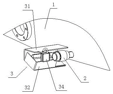
[0014] see figure 1 , figure 2 and image 3 As shown, a locomotive anti-theft fuel tank includes a fuel tank body 1, and an oil discharge device 2 is arranged at the bottom of the fuel tank body 1, and the oil discharge device 2 is covered in an anti-theft box 3 installed and fixed on the fuel tank body 1 . The oil drain device 2 is a stop valve or a screw plug.

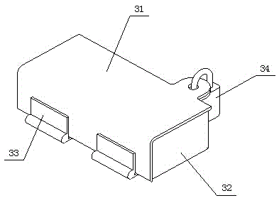
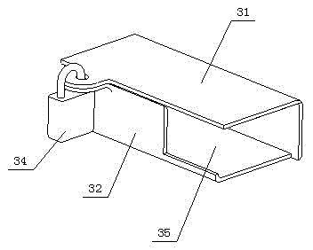
[0015] see figure 2 and image 3 , the anti-theft box 3 includes a left box body 31 and a right box body 32, the bottom of the left box body 31 is fixed on the fuel tank body 1, one side of the left and right box bodies 31, 32 is connected by a hinge 33, and the other side is connected by a lock 34 locking, form one end closure, the box body of other end opening 35, right box body 32 can rotate around the connecting shaft with left box body 31.

[0016] see figure 1 , when insta...


PUM


Abstract

The invention discloses an anti-theft fuel tank of a locomotive. The fuel tank comprises a fuel tank body, wherein a fuel drainage device is arranged at the bottom of the fuel tank body and covered with an anti-theft box mounted and fixed on the fuel tank body. The fuel tank is simple in structure, reasonable in design and capable of effectively preventing fuel of the locomotive from being stolen and reducing the economic loss of a locomotive user.

Description

technical field [0001] The invention relates to a fuel tank, in particular to a locomotive anti-theft fuel tank. Background technique [0002] At present, the bottom of the fuel tank of diesel locomotives is equipped with oil drain devices such as oil drain valves, the main function of which is to facilitate the discharge of fuel or the dirt generated when cleaning the fuel tank. The locomotive fuel tank of the prior art is not provided with an anti-theft oil device, so that fuel oil is stolen frequently. [0003] How to solve this problem has become an urgent problem for those skilled in the art. Contents of the invention [0004] The purpose of the present invention is to provide a locomotive anti-theft fuel tank, which can completely solve the technical problem that locomotive fuel is easily stolen. [0005] The purpose of the present invention is achieved through the following technical solutions: [0006] An anti-theft fuel tank for a locomotive compris...

Claims


Application Information

Patent Timeline
Patent Type & Authority Applications(China)
IPC IPC(8): B61C17/02
CPCB61C17/02
Inventor 张俊琰焦小燕范祖和宋建林
Owner CRRC ZIYANG CO LTD
Why Eureka
Try Eureka