Wheel-receiving device of model airplane

A technology of model airplanes and wheel parts, applied in toy airplanes, entertainment, toys, etc., can solve the problems of incomplete arrival, model airplane fuselage hitting the ground, rebounding, etc., to achieve safe take-off and landing, and ensure the safety of the fuselage

Inactive Publication Date: 2008-04-16
伊比虎模型有限公司
View PDF0 Cites 7 Cited by
  • Summary
  • Abstract
  • Description
  • Claims
  • Application Information

AI Technical Summary

Problems solved by technology

[0004] Although this wheel retracting device can achieve the purpose of sliding and retracting, in actual operation, because the pneumatic cylinder 2 starts at a fast speed, when the linkage rod 203 is linked with the rapid expansion and contraction of the piston rod 202, It will collide with the side end of the guide groove 405 at a very fast speed, which will not only cause a rebound, but also the linkage rod 203 will often not be smoothly nested in the embedded part 405 ", so that after the model aircraft takes off , the wheel body unit 3 cannot fully reach the wheel retracting position, and when the model aircraft is about to land, the wheel body unit 3 cannot fully reach the take-off and landing position, that is to say, the linkage rod 203 will be located between the arc segment 405' and the embedded position. The engaging part 405" is not locked and positioned by the engaging part 405", so that the shaft 302 cannot be kept upright stably, and when the wheel 303 touches the ground and is subjected to force, it may affect the wheel 303. The linkage rod 203 slides along the arc segment 405' and causes the shaft rod 302 to be skewed, and the fuselage of the model aircraft may hit the ground and be damaged

Method used


Image

  • Wheel-receiving device of model airplane
  • Wheel-receiving device of model airplane
  • Wheel-receiving device of model airplane

Examples


Embodiment Construction

[0020] Below in conjunction with accompanying drawing and embodiment the present invention is described in detail:

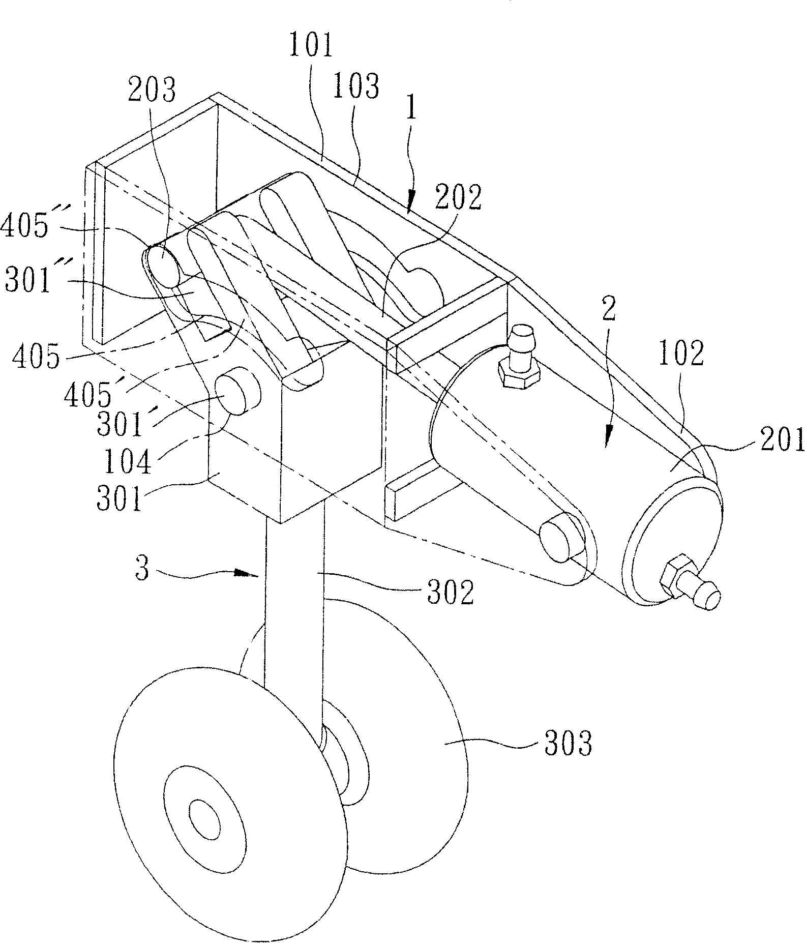
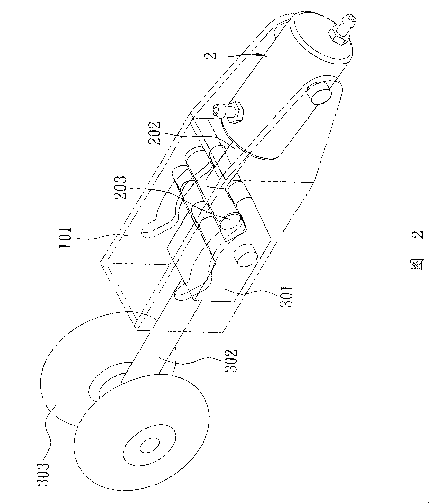
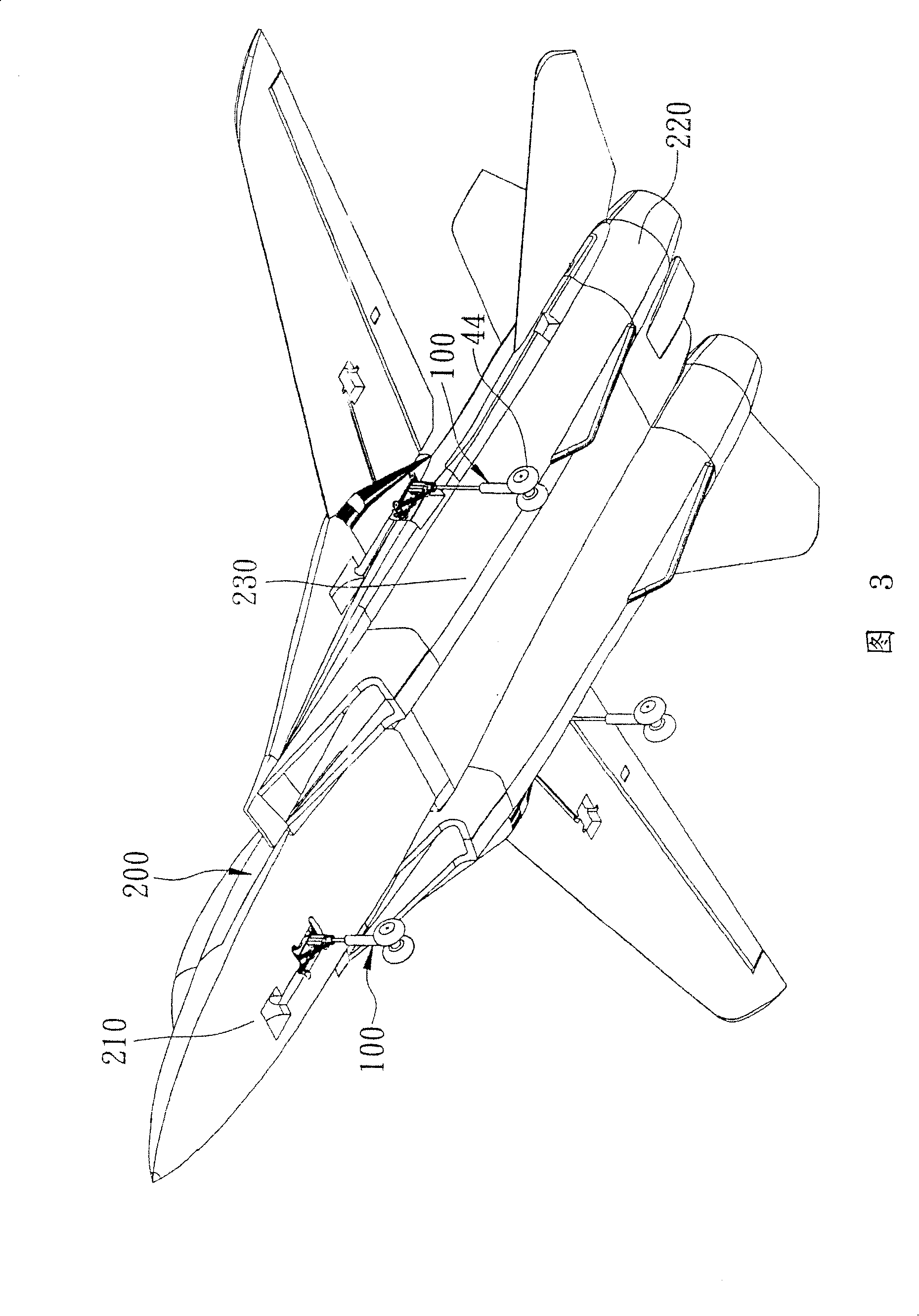
[0021] As shown in Figure 3, the preferred embodiment of the wheel retracting device 100 of the model aircraft of the present invention, the model aircraft also includes a fuselage 200, the fuselage 200 has a nose 210, and a nose 210 oppositely arranged Tail 220 and a belly 230 between the nose 210 and the tail 220, and the wheel receiving device 100 is installed on the bottom of the nose 210 and the bottom of both sides of the belly 230, as another example Figure 4 , Figure 5 As shown, the wheel receiving device 100 includes a housing unit 10, a driving unit 20 installed inside the housing unit 10, a connecting rod group 30 installed inside the housing unit 10 and driven by the driving unit 20 And a wheel body unit 40 that is pivoted by the link group 30 .

[0022] The housing unit 10 is in the shape of a rectangular hollow shell, and has a peripheral wall ...


PUM


Abstract

The present invention provides a wheel contracting device of the model airplane which includes a driving unit, a connecting rod group driven by the driving unit and a wheel body unit that is interlinked by the connecting rod group and generates pivoting. The driving unit has one motor and a driving wheel group, a first connecting rod of the connecting rod group is driven by one output wheel of the driving wheel group and can generate pivoting, the wheel body unit has one pivoting part, a swinging part and at least one wheel part that is axially arranged one the swinging part, and one second connecting rod of the connecting rod group is articulated between the articulating part and the swinging part. When the driving unit is actuated the wheel body unit is switched from a wheel contracting position to a rising-and-falling position by the connecting rod group. The present invention uses the driving of the driving unit and the interlocking of the connecting rod group, and causes that the wheel body unit surely oriented at the wheel contracting position and rising-and-falling position to achieve the purpose of safely rising and falling and guaranteeing the safety of the airframe.

Description

technical field [0001] The invention relates to a model toy, in particular to a wheel retracting device for a model airplane. Background technique [0002] like figure 1 As shown, there is an existing wheel retracting device for a model aircraft, which includes a housing unit 1, a pneumatic cylinder 2 pivotally arranged on the housing unit 1, and a pneumatic cylinder 2 pivotally arranged in the housing unit 1 and supported by the housing unit 1. The wheel body unit 3 driven by the pneumatic cylinder 2 . The housing unit 1 has a main body 101 and two lugs 102 fixed on the sides of the main body 101, the main body 101 has two oppositely arranged side plates 103, and two oppositely arranged side plates 103 bottoms. Pivot hole 104 and two guide slots 405 oppositely arranged above the pivot hole 104, each of the guide slots 405 has an arc segment 405' and two end portions on both sides of the arc segment 405' and upward The extended embedded part 405 ". The pneumatic cylinder ...

Claims


Application Information

Patent Timeline
Patent Type & Authority Applications(China)
IPC IPC(8): A63H27/32
Inventor 颜丽华
Owner 伊比虎模型有限公司
Why Eureka
Try Eureka