Butt hinge of folding case and folding case

A folding box and hinge technology, which is applied to pin hinges, folding panels, door/window accessories, etc., can solve problems such as hidden safety hazards, laborious operation, and large resistance, and achieve the effect of improving safety.

Inactive Publication Date: 2008-04-16
田东县永高林下养鸡协会
View PDF0 Cites 11 Cited by
  • Summary
  • Abstract
  • Description
  • Claims
  • Application Information

AI Technical Summary

Problems solved by technology

[0008] But the weight of the end wall 2' of the folding box is between 400 kilograms and 500 kilograms, and in the operation of inserting the locking pin and withdrawing from the locking pin, the resistance produced by the weight is relatively large, that is to say, the existing Although the hinge device can well realize the locking of the end wall in the u

Method used


Image

  • Butt hinge of folding case and folding case
  • Butt hinge of folding case and folding case
  • Butt hinge of folding case and folding case

Examples


Embodiment 1

[0124] Figure 4 to Figure 11 Shown is a first embodiment of the invention.

[0125] The hinge of the folding box of the present invention comprises: a fixed hinge plate 2, a movable hinge plate 3, a revolving pin 4, a lock pin 5, a pedal 6 and an elastic locking device 7;

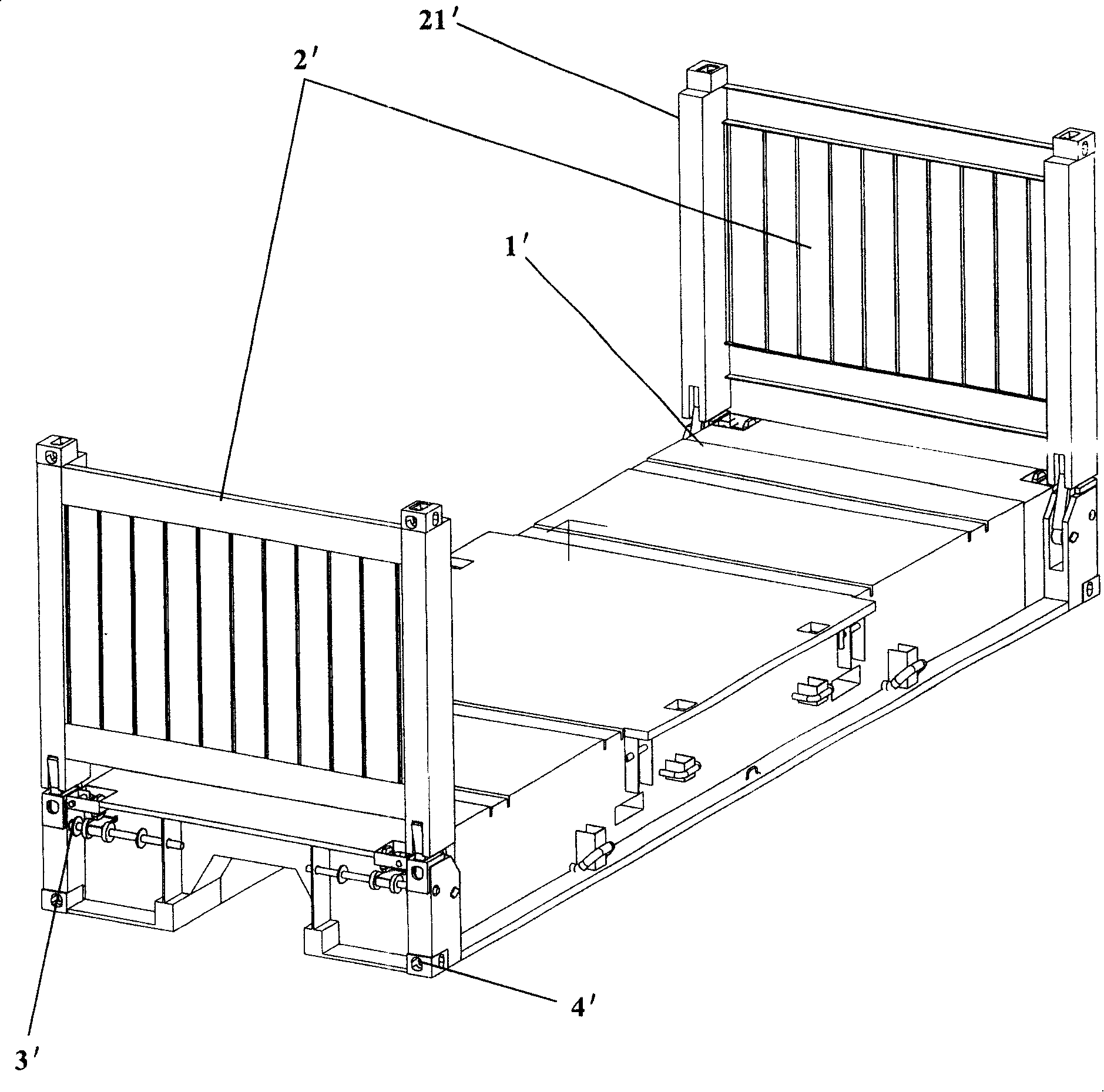
[0126] In this embodiment and other embodiments of the present invention, the movable hinge plate 3 is fixedly connected to the bottom of the corner post 9; the fixed hinge plate 2 is fixedly connected to the side of the end corner of the chassis 1, and the bottom corner piece 15 is fixedly connected At the bottom of the fixed hinge plate 2.

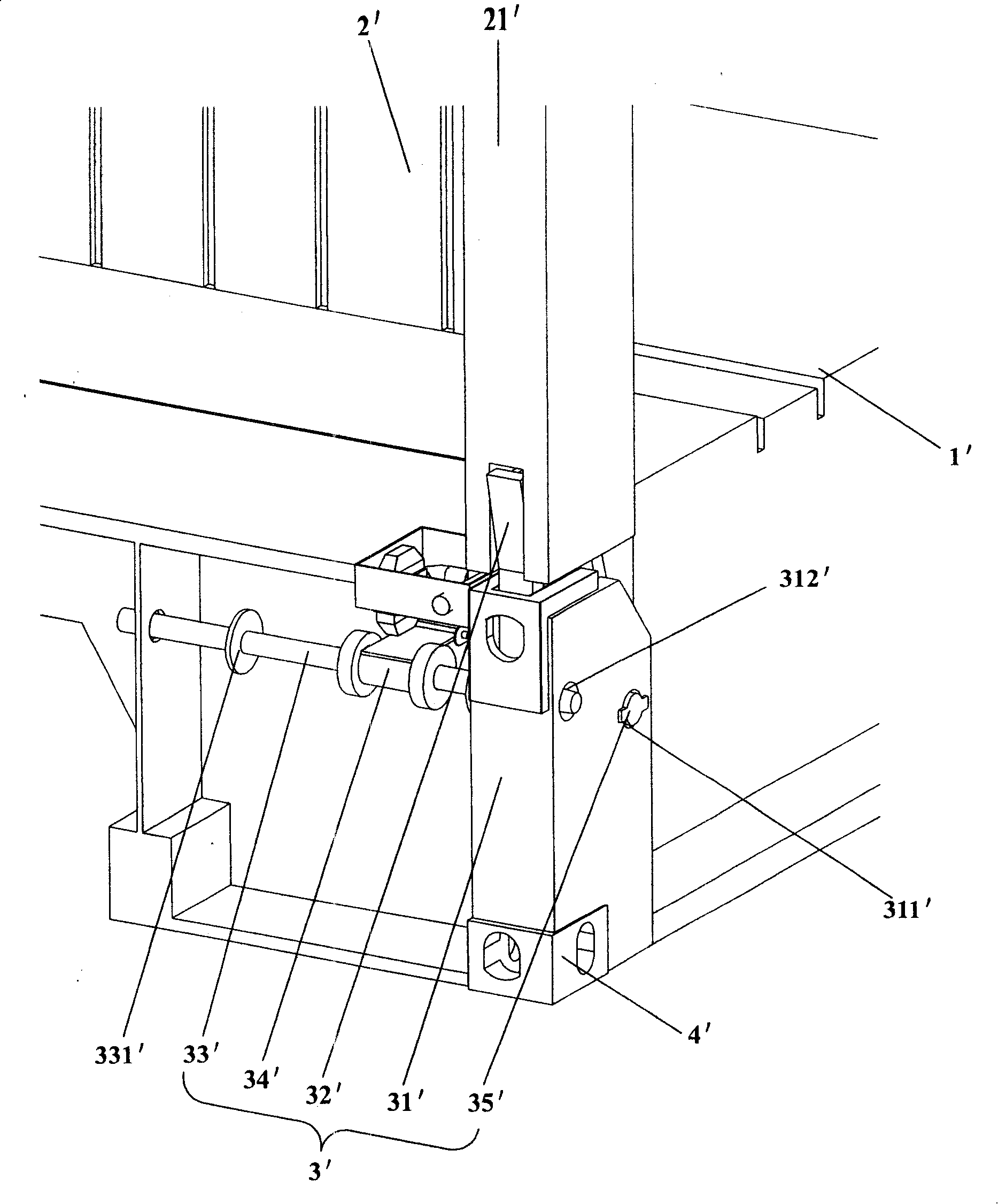
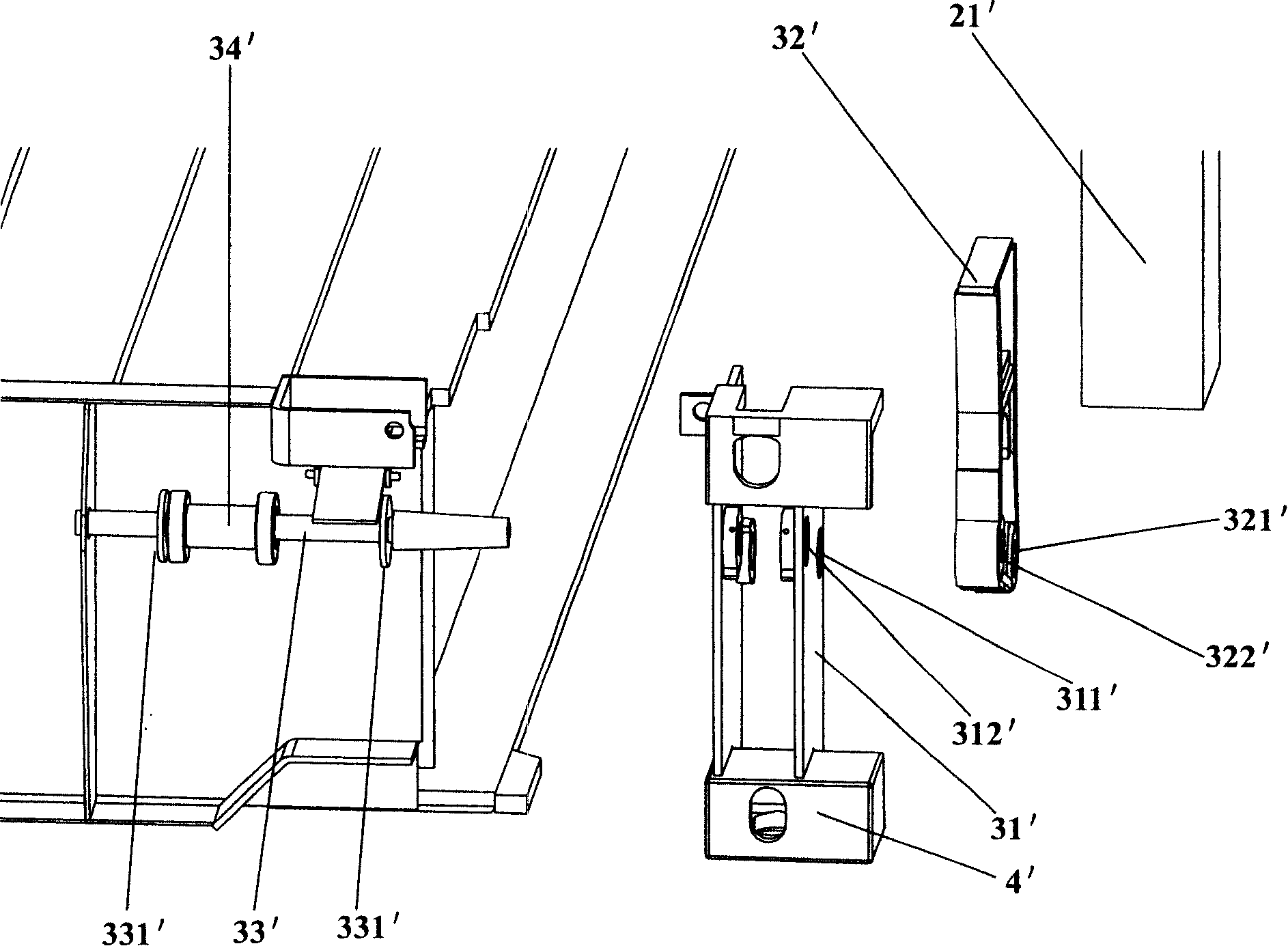
[0127] The fixed hinge plate 2 is set on the outside of the movable hinge plate 3; the fixed hinge plate 2 is provided with a fixed pivot hole 21, and the movable hinge plate 3 is correspondingly provided with a movable pivot hole 31, see Figure 5 and Figure 8A , the revolving pin 4 is inserted in the fixed pivot hole 21 and the movable pivot hole 31 to pivotall...

Embodiment 2

[0138] Figure 12 Shown is the second embodiment of the present invention, its structure is the same as that of the first embodiment, and a slide hammer 54 is added. In order to make the locking of the movable hinge plate 3 and the fixed hinge plate 2 by the lock pin 5 more reliable, a sliding hammer 54 is set on the base 51 of the lock pin 5, a hammering plate 55 is arranged on the base, and a locking part of the lock pin 5 After 53 is inserted in the fixed locking hole 22 and the sub-lock 32, knock the hammer plate 55 with a slide hammer 54 to make the locking of the movable hinge plate 3 and the fixed hinge plate 2 more reliable. The clamping plate 13 connected by the pin, at this moment, the clamping plate 13 can just lean against the inner side of the hammering plate 55 to prevent the locking pin 5 from receding and cause the locking of the movable hinge plate and the fixed hinge plate to be unstable.

Embodiment 3

[0140] Figure 13 to Figure 15 Shown is the third embodiment of the present invention, its structure is similar to the first embodiment, the difference lies in the structure and installation of the elastic locking device 7, the elastic locking device only includes the tension spring 72B, stretching One end of the spring 72B is hung on the hanging column 56 provided on the base 51 of the lock pin 5, and the other end is hung on the hanging column 14 fixedly connected to the end of the chassis 1, and the hanging column 14 is located away from the fixed hinge. Plate 2 nearer position and hanging post 56 are positioned at far away from fixed hinge plate 2; And the structure of spring seat 52 of lock pin 5 can be omitted, and this end of lock pin 5 directly passes on the vertical plate 11. The working principle of this embodiment is the same as that of the first embodiment, except that during the working stroke, the tension spring 72B is stretched, so that the tension spring 72B is...


PUM


Abstract

The invention provides a gemel of a folding carton and the folding carton, wherein, the gemel comprises a fixed flap, a movable flap, a rotating pin, a lock pin and an elastic locking device. The fixed flap is provided with a fixed pivotal hole and a fixed locking hole; the movable flap is correspondingly provided with a movable pivotal hole and a movable locking hole; the rotating pin is inserted in the fixed pivotal hole and the movable pivotal hole to connect the fixed flap and the movable flap in a pivotal way; the lock pin can be inserted in and separate from the fixed locking hole and the movable locking hole; the elastic locking device is connected between an underframe of the folding carton and the lock pin; the elasticity of the elastic locking device forces the lock pin to be in parallel move toward the direction along which the lock pin is inserted in the fixed locking hole and the movable locking hole. The invention ensures the safety and reliability of the locking of the gemel with easy and efforts-saving operation, shortened operating time and enhanced working efficiency.

Description

technical field [0001] The invention relates to a component of a container, in particular to a hinge device of a folding box. [0002] The invention also relates to a folding box incorporating such a hinge arrangement. Background technique [0003] In the field of containers, folding boxes are widely used because of their small stacking space after folding, low cost of empty container transshipment, and convenient loading and unloading of goods. [0004] As early as the mid-1970s, folding boxes have been designed, researched, and applied. However, the folding boxes at that time were transformed from dry cargo boxes. When carrying a load, they were used as a complete dry cargo box. The side walls are folded inward respectively, and then the top plate is put on, and then the end walls at both ends are folded toward the inside of the box. Although it can save the transportation cost of the empty box, the box type lacks universality due to the complicated operation; until the e...

Claims


Application Information

Patent Timeline
IPC IPC(8): E05D3/00E05D7/00B65D88/52
Inventor 兰民
Owner 田东县永高林下养鸡协会
Why Eureka
Try Eureka