
Small displacement engine exhaust manifold assembly structure

An exhaust manifold and assembly structure technology, which is applied to engine components, machines/engines, exhaust devices, etc., can solve the problems of low temperature and cannot meet emission standards, and achieve the effect of increasing length and good manufacturability

Inactive Publication Date: 2008-04-16
CHONGQING CHANGAN AUTOMOBILE CO LTD
View PDF0 Cites 5 Cited by
  • Summary
  • Abstract
  • Description
  • Claims
  • Application Information

AI Technical Summary

Problems solved by technology

[0002] With people's increasing emphasis on environmental protection and the country's stricter emission standards for automobiles, it is required that the three-way catalytic converter can be quickly ignited to solve the problem that the emission standard cannot be met due to the low temperature during cold start.

Method used


Image

  • Small displacement engine exhaust manifold assembly structure

Examples


Embodiment Construction

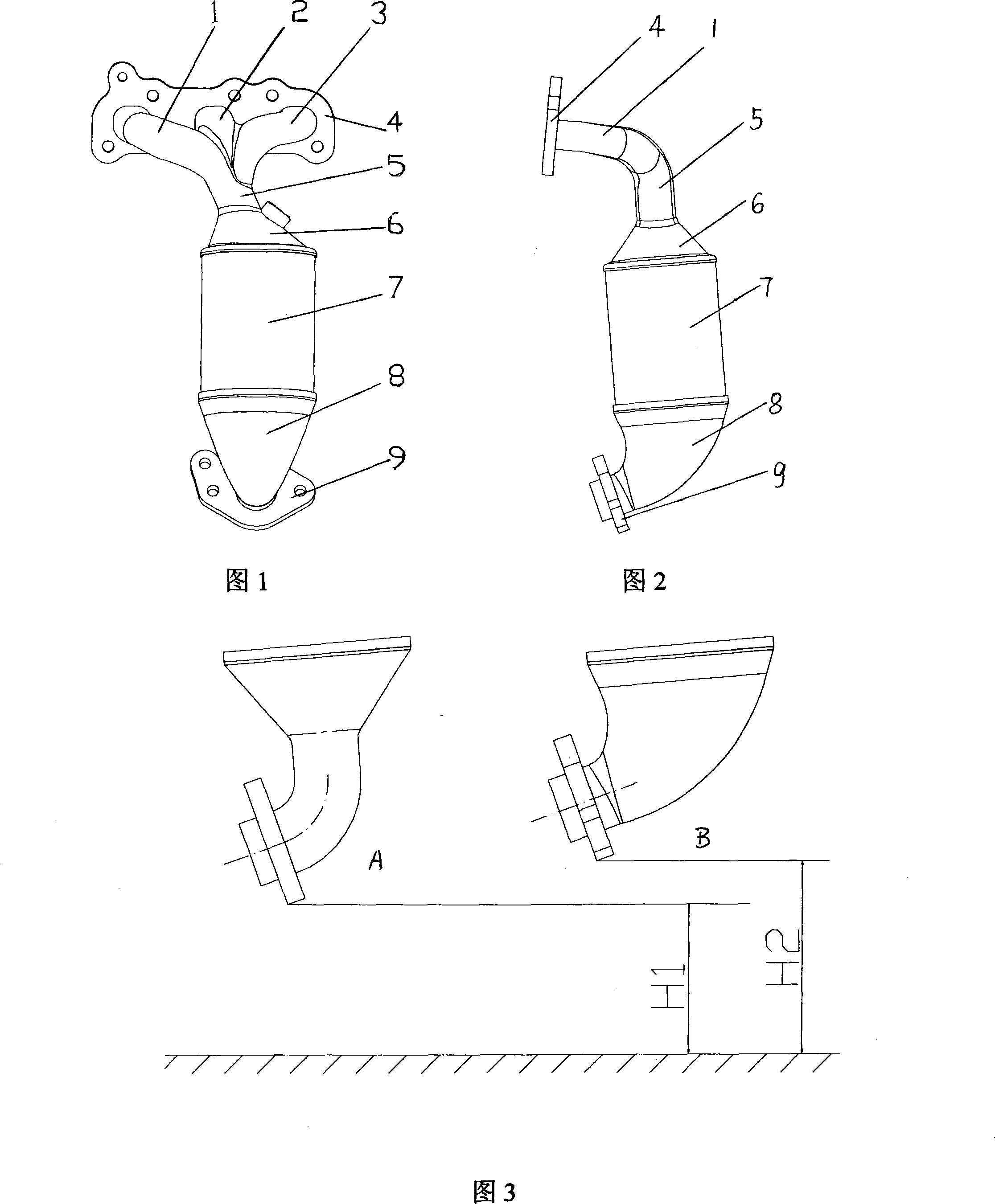
[0014] As shown in Figure 1, the exhaust manifold assembly is designed for a three-cylinder engine and is made of stainless steel. There are three exhaust manifolds for one, two and three cylinders. The blue plate 4 is welded, and the lower end is joined to the middle to form an air passage 5, which is welded to the inlet end cover 6 of the three-way catalytic converter, and the welding position deviates from the center of the inlet end cover 6 of the three-way catalytic converter by a certain angle. Each exhaust manifold air passage is welded by upper and lower half shells, and the lower half shell is integrated into one, namely air passage 5. The parting surfaces of each exhaust manifold air passage are on the same curved surface. . The outlet end cover 8 of the three-way catalytic converter adopts an angular structure and is connected to the outlet flange 9. The body of the three-way catalytic converter is a stainless steel barrel-shaped structure, and the upper and lower parts...


PUM


Abstract

The invention relates to a small engine exhaust collector assembly structure, and comprises two or three exhaust collector air flues, the upper ends of the exhaust collector air flues are welded with an inlet flange, the lower ends are connected with three way catalyst assembly, the lower end of the three way catalyst is connected with an outlet flange. The lower ends of the exhaust collector air flues are formed to one flue toward the middle part. Every exhaust collector air flue is formed by welding an upper half shell and a lower half shell, the lower half shell is an integrated one, die parting face of every exhaust collector air flue is on the same curved surface. The three way catalyst assembly is formed by welding an inlet end cover of the three way catalyst, the three way catalyst body and an outlet end cover of the three way catalyst, and adopts stainless material. The welding positions of the exhaust collector air flues deviate the center of the inlet end cover of the three way catalyst, the outlet end cover of the three-way catalyst adopts steerhorn structure. The invention has compact structure and high discharge standard, and can solve the problem of arranging the long exhaust collector and the catalyst in limited space.

Description

Technical field [0001] The invention belongs to the technical field of engines, and particularly relates to an engine exhaust manifold structure. Background technique [0002] As people pay more and more attention to environmental protection and the country has stricter and stricter vehicle emission standards, this requires the three-way catalytic converter to be able to quickly ignite to solve the problem that the temperature is too low during the cold start period to meet the emission standards. At the same time, for small-displacement engines equipped with smaller models, the ground clearance requirements are relatively high, and in order to meet the uniformity of the air duct exhaust, the exhaust manifold is required to have a certain length. Therefore, it is a difficult point in the current design to arrange a sufficiently long exhaust manifold and catalytic converter in a small space. Summary of the invention [0003] The purpose of the present invention is to provide a sm...

Claims


Application Information

Patent Timeline
Patent Type & Authority Applications(China)
IPC IPC(8): F01N7/10F01N3/28F01N13/10
Inventor 瞿尚胜李琨卿辉斌
Owner CHONGQING CHANGAN AUTOMOBILE CO LTD
Learn More