Filter assembly

A filter assembly and filter cloth technology, applied in the field of electric control boxes, can solve the problems of flow attenuation that cannot be calculated by users, danger, and poor air flow performance.

Active Publication Date: 2008-04-16
GIANUS
View PDF0 Cites 1 Cited by
  • Summary
  • Abstract
  • Description
  • Claims
  • Application Information

AI Technical Summary

Problems solved by technology

[0003] In this known system, the fan applied to the filter assembly must overcome the resistance to the air passing through the filter, which resistance occurs due to load leakage, which increases the pressure that the fan must exceed, resulting in poor performance of
[0004] In particular, when filter clogging increases, further flow decay cannot be calculated by the user and often falls (even faster in very dirty gases) to the minimum value that guarantees adequate cooling of the device placed in the electrical control box the following
[0005] In this case, one solution that has been adopted is to provide the box with a thermostat that is triggered when the limit temperature is reached, but this thermostat needs to measure the temperature at a single point, and as the flow decreases, the internal Ventilation (meaning the agitation of the air inside the electrical box) is correspondingly reduced, which can create dangerous and uncontrollable localized "hot spots"

Method used


Image

  • Filter assembly
  • Filter assembly

Examples


Embodiment Construction

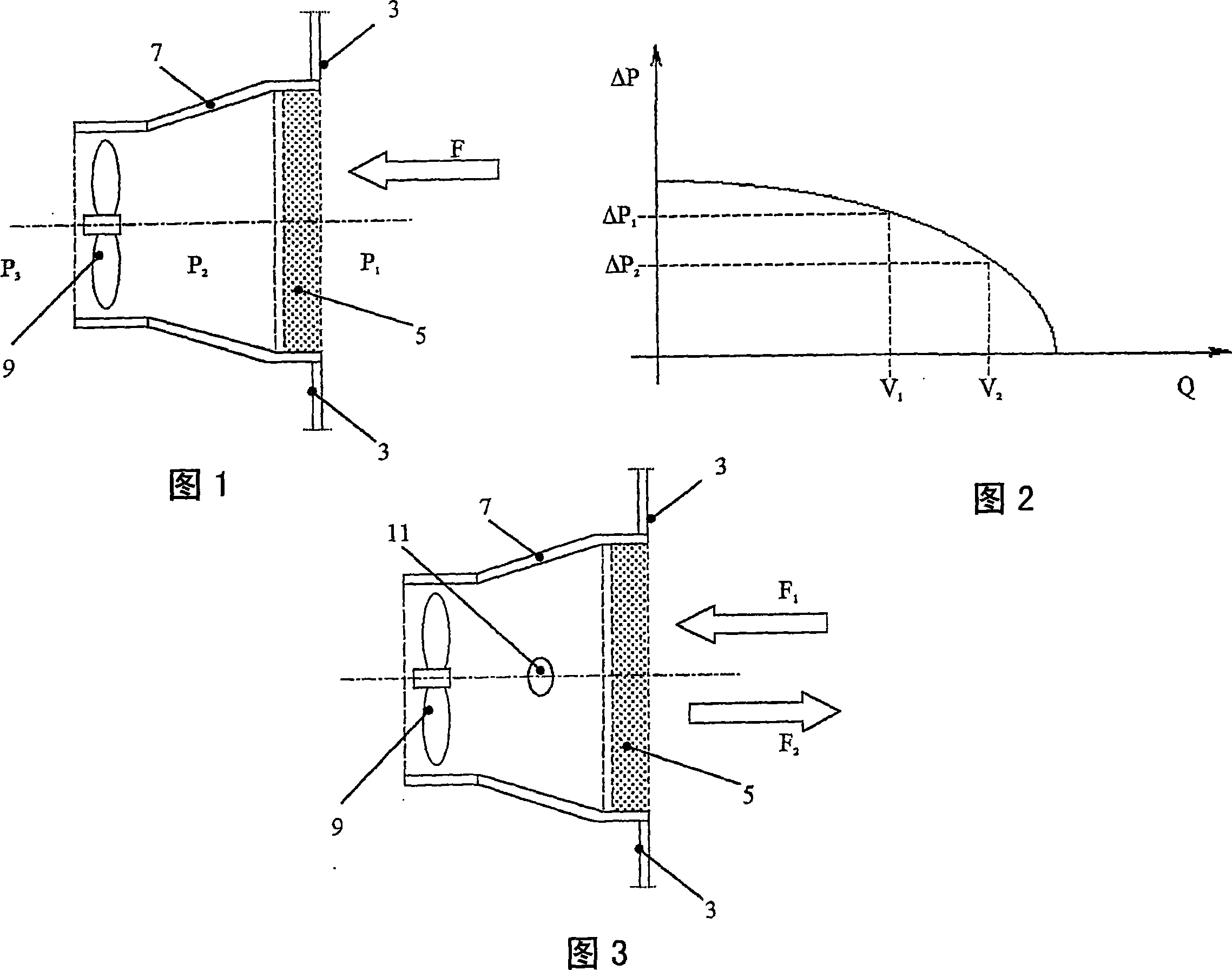
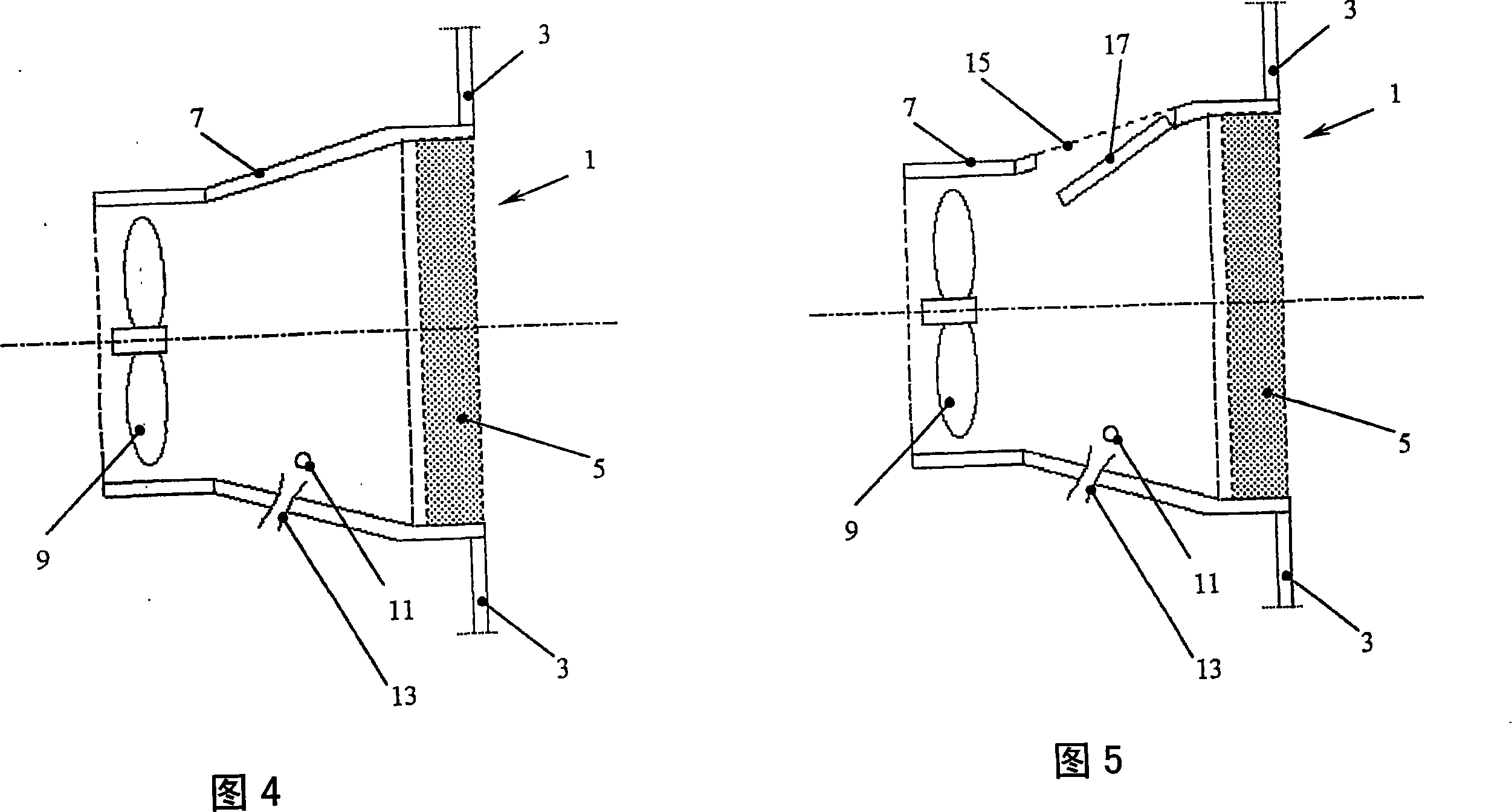
[0026] Referring to Figure 1, a prior art filter assembly for an electrical cabinet can be noted. This filter assembly is inserted into the wall 3 of the electric control box, as is known, from the outside of the box to the inside of the box in the direction of air flow F, consisting of a filter cloth 5, a delivery box 7 and a fan 9; In construction, three pressure ranges are generally defined: external pressure P1, intermediate pressure P2 between filter cloth 5 and fan 9 (equal to P1 minus filter load leakage), and internal head pressure P3 (equal to p2 minus fan prevalence). As mentioned earlier, it is clear that the fan 9 has to exceed the air passage resistance of the filter cloth 7, which occurs with load leakage which increases the pressure the fan has to overcome, subsequently degrading the performance in terms of air flow.

[0027] In order to measure the flow of air, two different modes of operation can be referred to: in the first case the flow will be measured dir...


PUM


Abstract

An improved filter assembly (1) is disclosed, particularly for electric cabinets, comprising a filter cloth (5), a conveying sump (7) and a fan (9), equipped with at least one thermal-resistive sensor (11) placed next to at least one hole (13) obtained in the conveying sump (7).

Description

technical field [0001] The present invention relates to an improved filter assembly, particularly for electrical cabinets. Background technique [0002] In the prior art, for cooling electrical dashboards, air filtration systems are used equipped with fans (axial, radial, etc. types) adapted to force air through filter cloths adapted to filter the air. [0003] In this known system, the fan applied to the filter assembly must overcome the resistance to the air passing through the filter, which occurs due to load leakage, which increases the pressure that the fan must exceed, resulting in a performance deteriorates. [0004] In particular, when filter clogging increases, further flow decay cannot be calculated by the user and often falls (even faster in very dirty gases) to the minimum value that guarantees adequate cooling of the device placed in the electrical control box the following. [0005] In this case, one solution that has been adopted is to provide the box with ...

Claims


Application Information

Patent Timeline
Patent Type & Authority Applications(China)
IPC IPC(8): F24F13/28F24F11/00F24F11/02
CPCF24F2001/0096H05K7/20181F24F11/001F24F2011/0038F24F11/0012F24F11/0086F24F11/30F24F2110/00F24F2110/10F24F2110/30F24F1/0071
Inventor 罗伯托·布里奥斯基
Owner GIANUS
Why Eureka
Try Eureka