Eureka AIR delivers breakthrough ideas for toughest innovation challenges, trusted by R&D personnel around the world.

Electrostatic chuck device

An electrostatic chuck, electrostatic adsorption technology, applied in the application of electrostatic attraction holding devices, circuits, electrical components, etc., can solve the problem of difficulty in manufacturing large-sized electrostatic chucks, high prices, and reduce the operation rate and equipment. There are several, the effect of preventing discharge

Inactive Publication Date: 2008-04-23
SHIN ETSU ENG
View PDF2 Cites 0 Cited by
  • Summary
  • Abstract
  • Description
  • Claims
  • Application Information

AI Technical Summary

Problems solved by technology

[0004] Conventionally, in a substrate laminating machine that stacks two substrates in a vacuum, the substrate is held by an electrostatic chuck. However, in recent years, with the increase in the size of the substrate, it is difficult to manufacture a large-sized electrostatic chuck, and even if it can be manufactured become a very high priced item

Method used


Image

  • Electrostatic chuck device
  • Electrostatic chuck device
  • Electrostatic chuck device

Examples


Embodiment 1

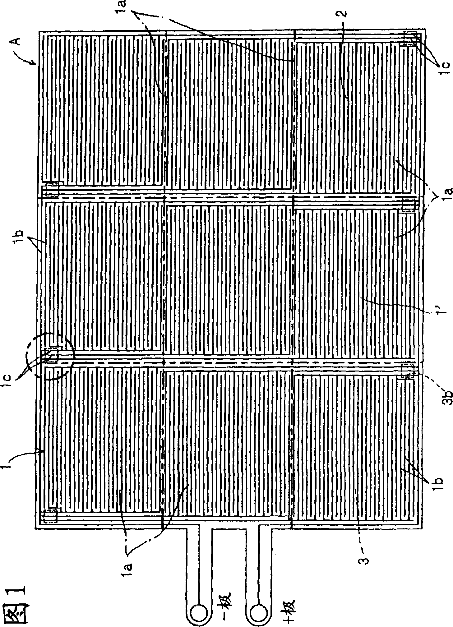
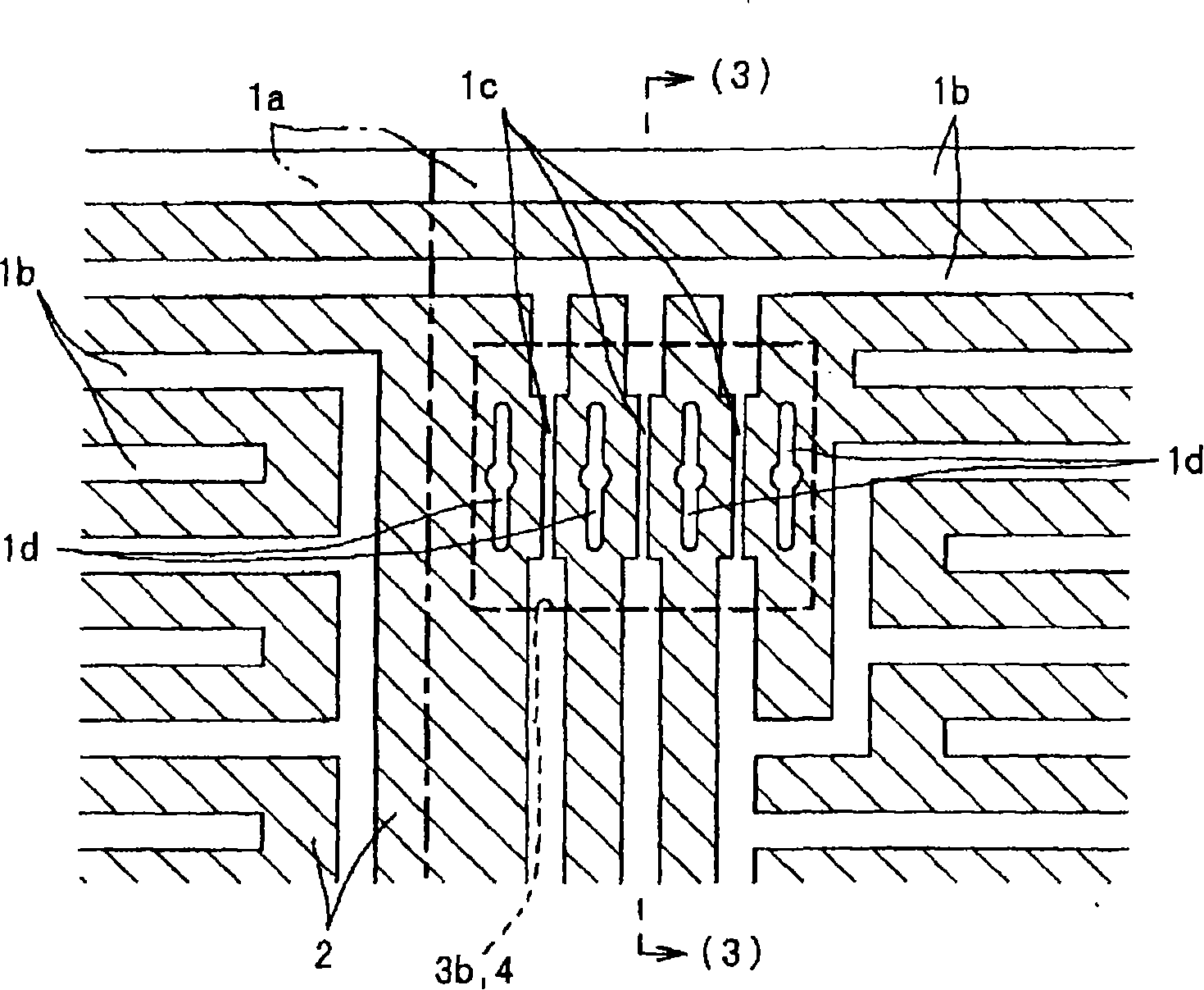
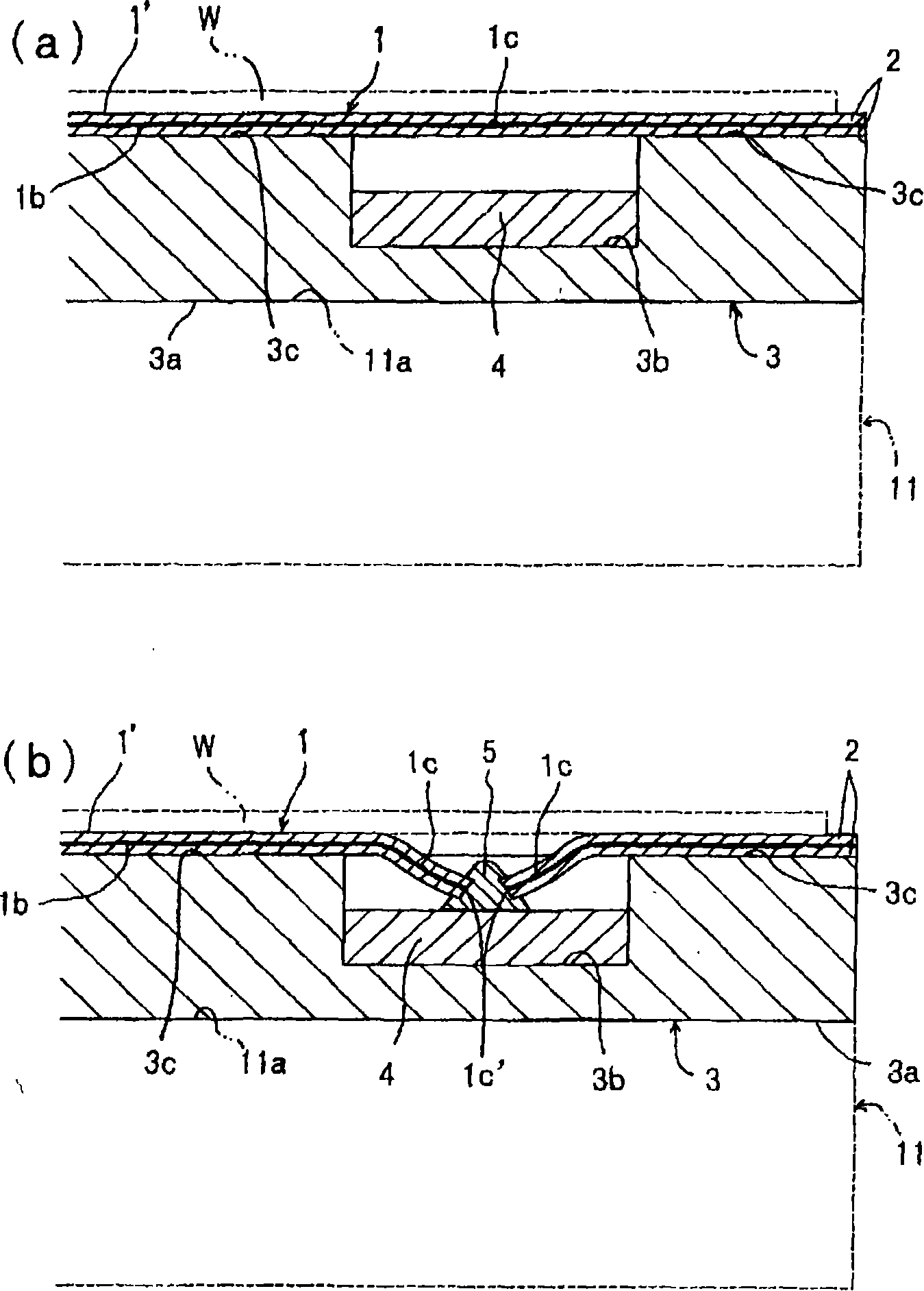
[0072] Figure 1~ image 3 As shown, this embodiment 1 shows that the above-mentioned electrode pattern 1b is a bipolar electrostatic chuck with a + pole electrode and a - pole electrode, and these + pole and - pole electrode patterns 1b are inserted and sealed in a polyimide Among the dielectric layers 2 made of engineering plastics such as amine or polyetheretherketone (PEEK), at the same time, the above-mentioned multiple power supply parts 1c are dispersed and arranged on the inner area of ​​the electrostatic chuck function surface 1', thereby forming an electrostatic chuck with an integrated structure. The chuck film is bonded to the metal pedestal 3, and the concave portion 3b is formed on the surface 3c of the pedestal 3 so as to face the above-mentioned power supply part 1c.

[0073] In the illustrated example, the above-mentioned area 1a has a rectangular shape, and the + pole and - pole of the above-mentioned electrode pattern 1b are respectively formed in the shape o...

Embodiment 2

[0089] This embodiment 2, as shown in Fig. 4~ Figure 5 As shown, the above-mentioned plurality of power supply parts 1c are scattered and arranged in the outer area of ​​the electrostatic chuck function surface 1' facing the workpiece W and provided with the electrode pattern 1b, thereby forming an electrostatic chuck film with a bendable integral structure, And these outwardly protruding power supply parts 1c are bent and fixed along the side surfaces 3d of the pedestal 3, or are bent and fixed by bonding so as to reach the back surface 3a of the pedestal 3, and on the side surfaces 3d of the pedestal 3 Or form the concave portion 3b on the back surface 3a, so that the structure of the cut part 1c' of the cut power supply part 1c is sealed, which is different from the above-mentioned Figs. image 3 Shown embodiment 1, the structure outside it and Fig. 1~ image 3 Example 1 shown is the same.

[0090] Therefore, in Figure 4- Figure 5 In the illustrated embodiment 2, the s...

Embodiment 3

[0094] The structure of this embodiment 3, such as Figure 6 ~ Figure 7 As shown, for the bendable electrostatic chuck film in which the above-mentioned plurality of power supply parts 1c are distributed and arranged in the outer region of the electrostatic chuck function surface 1', these power supply parts 1c are bent along the side 3d or the back surface 3a of the pedestal 3 And it is fixed by bonding, and the concave portion 3b formed opposite to the above-mentioned power supply unit 1c on the side 3d or the back surface 3a is formed into a sealed structure that can be opened and closed, and the cut power supply unit 1c is placed inside it. The cut-off part 1c' is sealed, which is different from the above-mentioned Fig. 1- image 3 The embodiment 1 shown and Fig. 4~ Figure 5 Shown embodiment 2, the composition outside it and in Fig. 1~ image 3 shown in Example 1 and in Figures 4- Figure 5 Example 2 shown is the same.

[0095] In the illustrated example, the pedestal...


PUM


Abstract

An electrostatic chuck apparatus is recovered to attract a work in a short time by a simple process. An electrode (1) is divided into a plurality of areas (1a) within a plane parallel to the work (W), independent electrode patterns (1b) are arranged for the areas (1a), respectively, power supply sections (1c) for the electrode patterns (1b) are arranged in the areas (1a), respectively, and power supply to the electrode pattern (1b) arranged on the discretionary area (1a) is partially stopped by cutting the discretionary power supply section (1c). Thus, even when a part of a film plane in the areas (1a) is destroyed, though the electrode pattern (1b) in the destroyed area (1a) selectively does not function as an electrostatic chuck, the electrode patterns (1b) in other areas (1a) function as electrostatic chucks.

Description

[0001] technology area [0002] The present invention relates to an electrostatic chuck device, which is used, for example, to absorb and hold glass substrates such as CF glass or TFT glass or synthetic resin substrates in the manufacturing process of flat panel display panels such as liquid crystal displays (LCDs) and plasma displays (PDPs). A substrate assembly device of a substrate bonding machine that bonds workpieces such as substrates, a substrate transfer device that transfers substrates, or a semiconductor manufacturing device that processes workpieces such as silicon wafers. [0003] More specifically, the present invention relates to an electrostatic chuck device that electrostatically attracts a workpiece by applying a voltage to an electrode arranged in a planar shape facing the workpiece. Background technique [0004] Conventionally, in a substrate laminating machine that stacks two substrates in a vacuum, the substrate is held by an electrostatic chuck. However, ...

Claims


Application Information

Patent Timeline
Patent Type & Authority Applications(China)
IPC IPC(8): H01L21/68H02N13/00B24B41/06H01L21/683
CPCH01L21/6833H02N13/00H01L21/687
Inventor 大谷义和
Owner SHIN ETSU ENG
Why Eureka
Eureka Blog
Learn More