Method for producing a tubular flat knit fabric with the plating technique

A knitted fabric and cylinder technology, which is applied in the field of making circular knitted fabrics, can solve the problems of shrinking edge loops and the like

Inactive Publication Date: 2008-04-30
H STOLL GMBH & CO KG
View PDF0 Cites 17 Cited by
  • Summary
  • Abstract
  • Description
  • Claims
  • Application Information

AI Technical Summary

Problems solved by technology

These drawbacks are therefore attributable in particular to the fact that the thread guide moves away from the knitted fabric pulling together the loops of the edge needles and thus shrinking the edge loops

Method used


Image

  • Method for producing a tubular flat knit fabric with the plating technique
  • Method for producing a tubular flat knit fabric with the plating technique
  • Method for producing a tubular flat knit fabric with the plating technique

Examples


Embodiment Construction

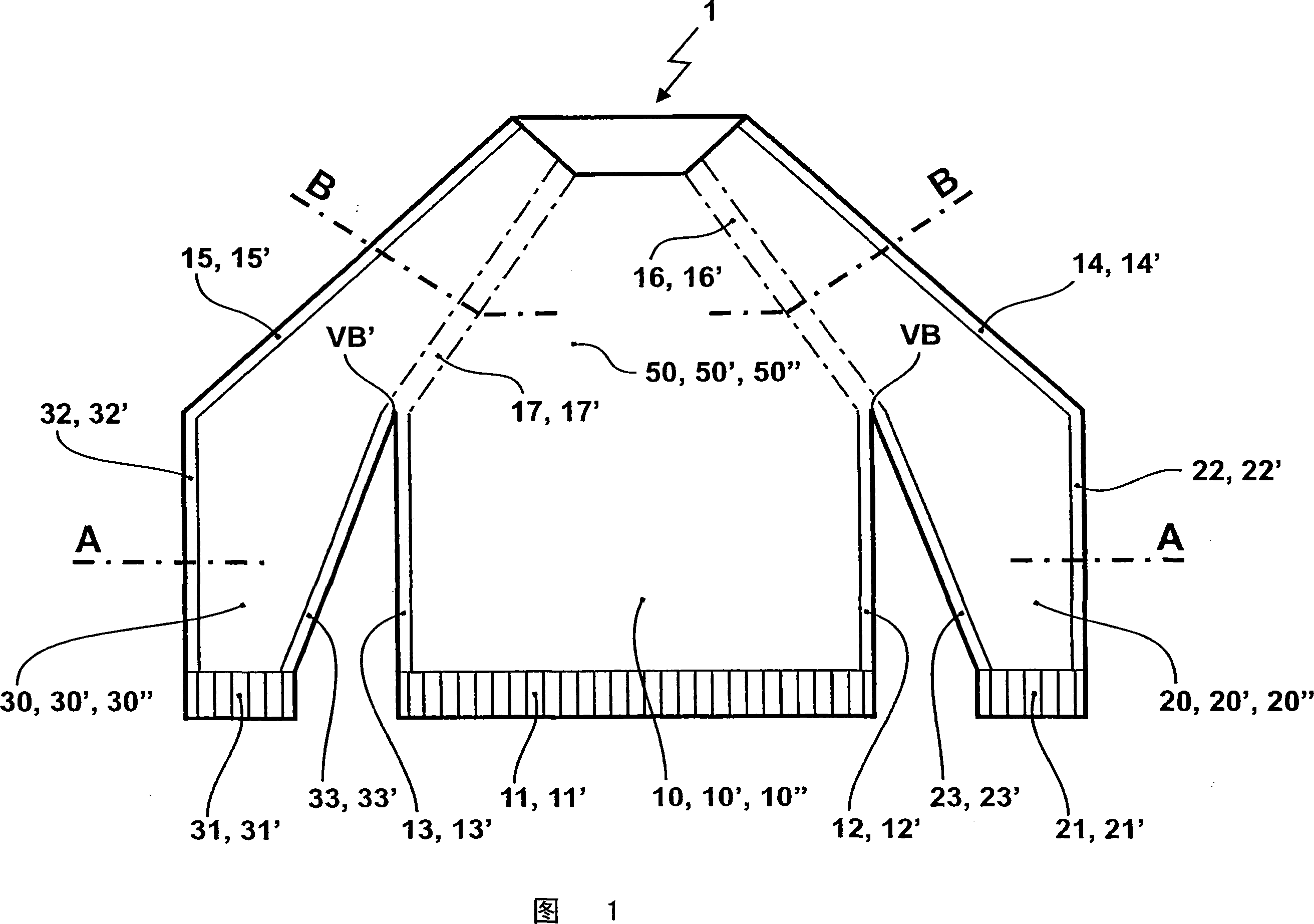
[0018] Fig. 1 shows a pullover formed as a tubular formed product knit, which can be integrally formed on a flat knitting machine. The pullover 1 is made using the plating technique, ie, to make the pullover 1 at least two different knitting threads are supplied to each needle involved in the knitting process in order to form loops.

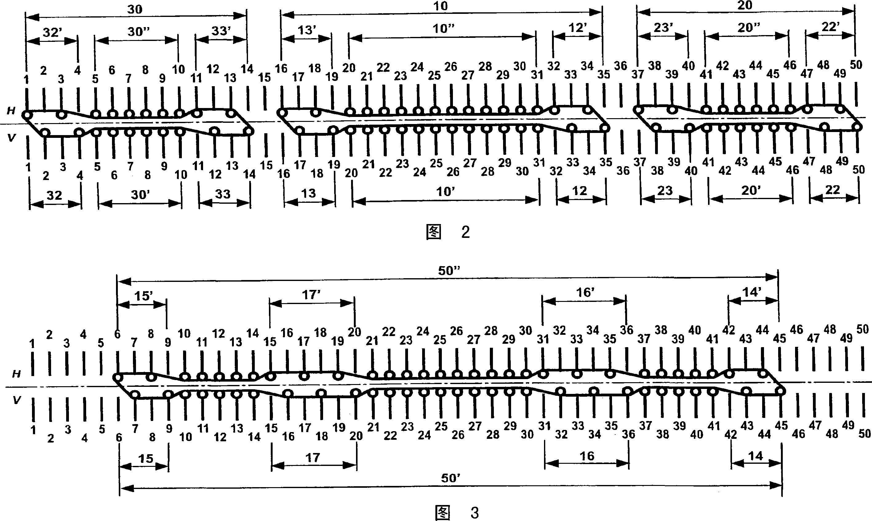
[0019] The sequence of the knitting sequence to form the tubular former knitted fabric 1 is consistent with the prior art. It starts with three separate circular knits, a body part 10 , a left sleeve 20 and a right sleeve 30 . Each of the three tubes 10, 20, 30 is supplied with knitting thread via a separate thread guide. Then, from the connecting regions VB, VB' where the left sleeve 20 and the right sleeve 30 are sewn to the body part 10, the knitted fabric is formed into a single circular knitted fabric 50. In this area, the knitting thread is generally supplied by a yarn feeder.

[0020] In the example shown, ribbing is located at the unde...


PUM


Abstract

The method involves changing a knitting direction according to formation of edge stitches of a knitted hosiery garment. The edge stitches in a row is enlarged / increased to another row by a transferring process such that the edge stitches have the same size as that of the remaining stitches of the knitted hosiery garment. The stitches in the formed row are transferred to a needle bed and are knitted as needle stitches. Edge areas (12, 12', 13, 13') are formed with needle stitches.

Description

technical field [0001] The present invention relates to a method for producing circular formed product knitted fabrics using plating knitting technology on a flat knitting machine with at least two opposing needle beds. Background technique [0002] Single-jersey smooth knitted fabrics produced by plated knitting technology include an inner side formed by added threads and an outer side formed by core threads. Add wires and core wires are usually of different qualities and often of different colours. Circular shaped knitted fabrics made with plating technology have so-called plating defects at those locations where the thread guide changes its direction of movement, ie in particular at the sides of the body parts and sleeves. These drawbacks are therefore attributable in particular to the fact that the yarn guide moves away from the knitted fabric, pulling together the loops of the edge needles and thus reducing the edge loops. At these reduced coils, the added wire is usu...

Claims


Application Information

Patent Timeline
Patent Type & Authority Applications(China)
IPC IPC(8): D04B7/32D04B15/00
CPCD10B2403/0114D04B1/246D04B1/24D04B1/106
Inventor T·农嫩马彻F·克卢拉
Owner H STOLL GMBH & CO KG
Why Eureka
Try Eureka