
Image forming apparatus and control method thereof

An imaging device and image fixing technology, applied in the direction of temperature control using electric methods, instruments, and equipment using electrical recording technology using charge patterns, etc., can solve the problems of insufficient operational sensitivity, etc.

Inactive Publication Date: 2008-04-30
SAMSUNG ELECTRONICS CO LTD
View PDF0 Cites 6 Cited by
  • Summary
  • Abstract
  • Description
  • Claims
  • Application Information

AI Technical Summary

Problems solved by technology

However, even if the operating sensitivity is sufficient to prevent fires, such thermostats do not have sufficient operating sensitivity to preemptively prevent damage to components caused by high temperatures

Method used


Image

  • Image forming apparatus and control method thereof
  • Image forming apparatus and control method thereof
  • Image forming apparatus and control method thereof

Examples


Embodiment Construction

[0038] Reference will now be made in detail to the present embodiments of the invention, examples of which are illustrated in the accompanying drawings, wherein like reference numerals refer to like elements throughout. The embodiments are described below in order to explain the present invention by referring to the figures.

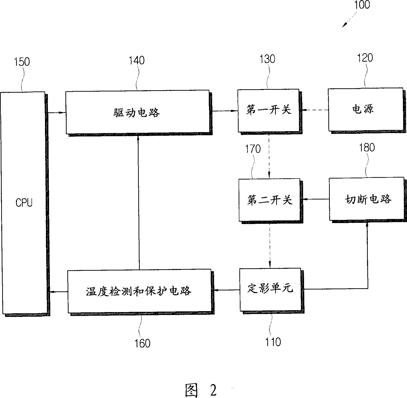
[0039] FIG. 2 is a block diagram illustrating the configuration of the imaging device 100 according to an exemplary embodiment of the present invention. The image forming apparatus 100 may include a laser printer, a photocopier, a facsimile, and a multifunction product. As shown in FIG. 2 , the image forming apparatus 100 includes a fixing unit 110 , a power source 120 , a first switch 130 , a driving circuit 140 , a CPU 150 , a second switch 170 and a cutoff circuit 180 . It should be understood that the imaging device has many other elements in addition to those listed above.

[0040] The fixing unit 110 includes: a fixing roller (not shown) and a he...


PUM


Abstract

An image forming apparatus includes a fixing unit (110) having a fixing roller and a heating roller to fix a toner image on a printing medium and a heater to heat the heating roller, a power supply (120) to supply power to the heater included in the fixing unit (110) along a power supply line, a first switch (130) operable to selectively supply the power from the power supply (120) to the heater, a main controller (150) arranged to control an operation of the first switch (130) to maintain a temperature of the fixing unit (110) within a predetermined fixing temperature range, a second switch (170) operable to open the power supply line between the power supply (120) and the heater, and an auxiliary controller (180) arranged to control an operation of the second switch (170) to open the power supply line if the temperature of the fixing unit (110) is outside the predetermined fixing temperature range.

Description

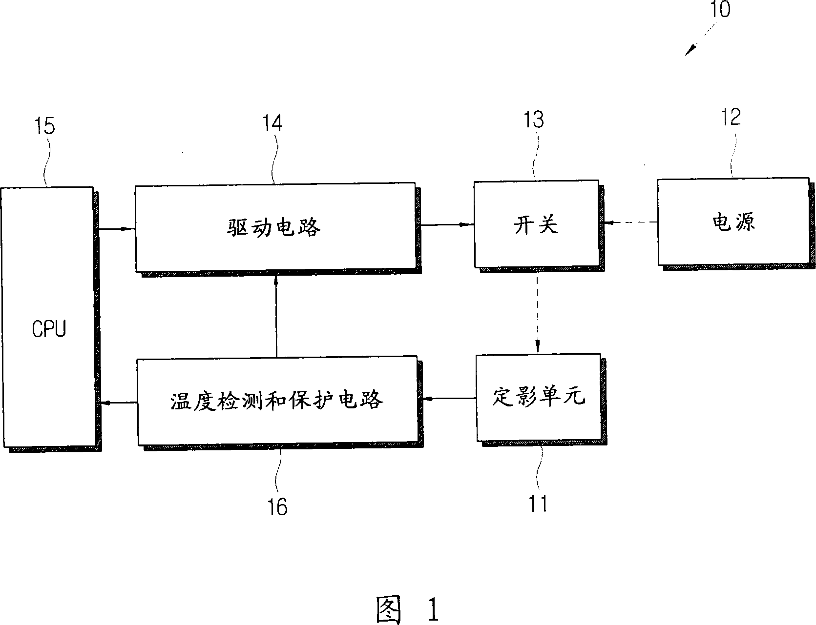
technical field [0001] Aspects of the present invention relate to an image forming apparatus and a control method thereof, and more particularly, to an image forming apparatus having a fixing unit and a control method thereof. Background technique [0002] Image forming apparatuses such as laser printers, photocopiers, facsimile machines, and multifunction products fix toner on a printing medium such as paper and form a toner image based on image data. FIG. 1 is a control block diagram of a conventional imaging device 10 . As shown in FIG. 1 , the image forming apparatus 10 includes a fixing unit 11 having a fixing roller (not shown) and a heating roller (not shown) for fixing a toner image onto a printing medium such as paper, and a A heater (not shown) in the heating roller so that the heating roller is heated; a power supply 12, which supplies power to the heater; power supply; drive circuit 14, which drives switch 13; temperature detection and protection circuit 16, wh...

Claims


Application Information

Patent Timeline
Patent Type & Authority Applications(China)
IPC IPC(8): G03G15/20G03G15/00G03G13/20G03G13/00G05D23/19
CPCG03G15/2078G03G15/2039G03G15/205G03G15/5004G03G15/80G03G2215/00978
Inventor 玄皓日
Owner SAMSUNG ELECTRONICS CO LTD
Learn More