

Sling device for a piece with force compensation and hoisting system comprising the same
A hoisting device and force technology, applied in the field of lifting systems, can solve problems such as unsatisfactory, system complexity, and large instantaneous electric power requirements
- Summary
- Abstract
- Description
- Claims
- Application Information
AI Technical Summary
Problems solved by technology
Method used
Image

Examples
Embodiment Construction
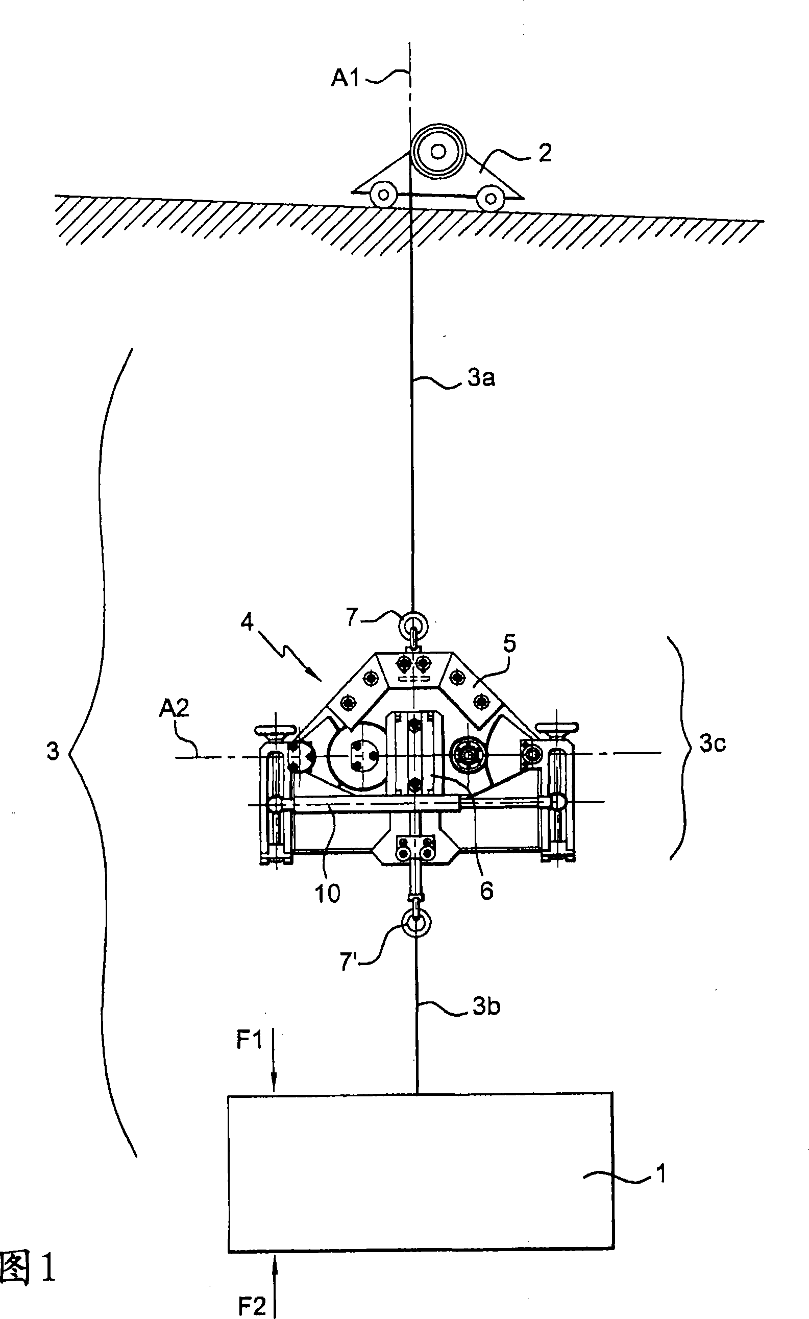
[0030] [30] The hoisting device shown in FIG. 1 has a winch 2 that moves on a guide rail and supports a member 1 held by a sling 3 .
[0031] [31] The winch moves on guide rails according to a control device not shown because it is customary. Likewise, the slings can be shortened or extended by winches in order to position the held member opposite a ground structure on which the held member has to be fitted.
[0032] [32] In fact, the winch can be replaced by any lifting device that utilizes a sling to lift the load.
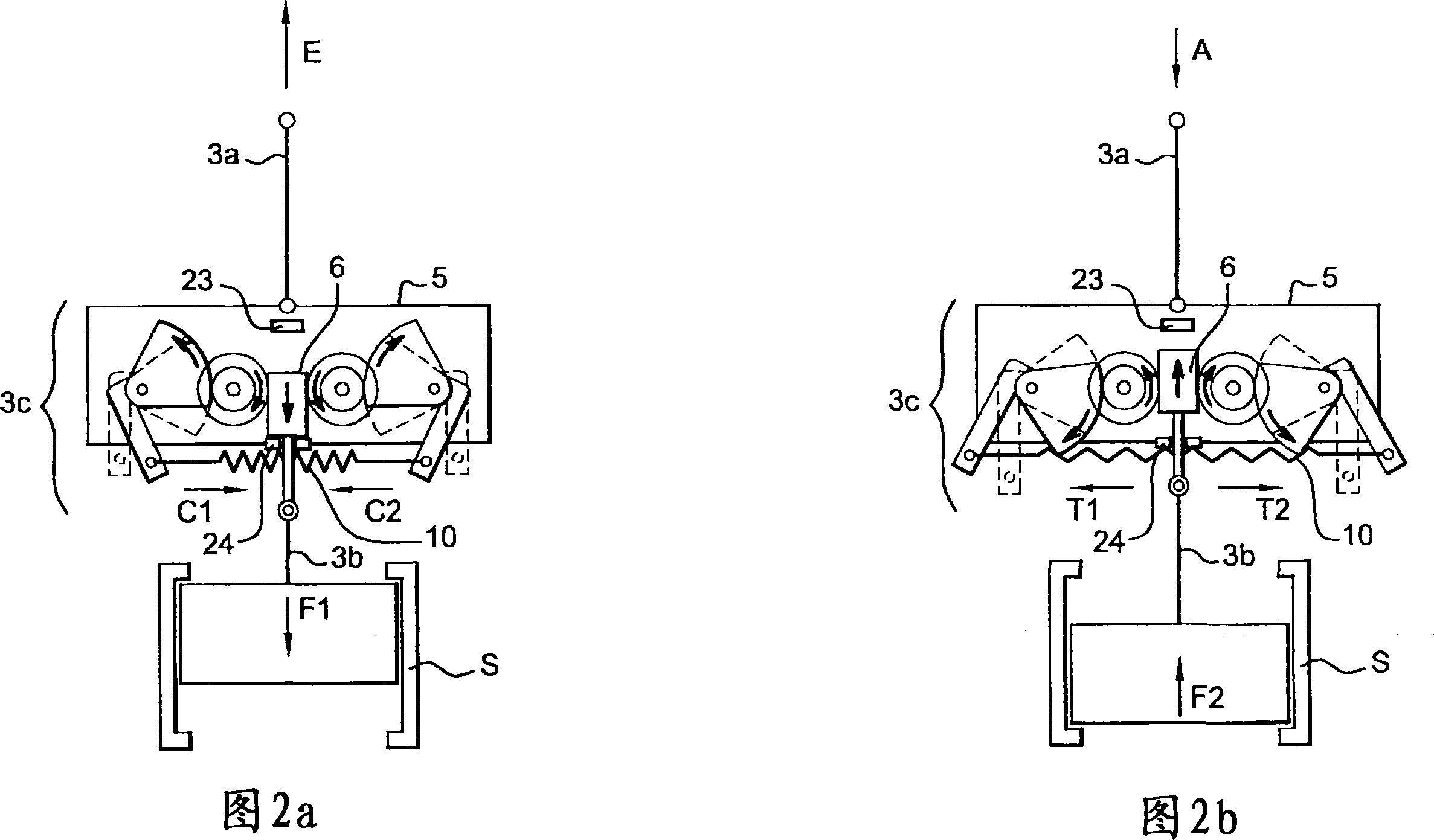
[0033] [33] According to the invention, the sling 3 is provided with a first inextensible portion 3a, which rests on a section 3c provided with spring elements 10, 10' which, under load, can For a limited variation of the load on the member 1, said spring members 10, 10' allow a limited range of elastic elongation or shortening of said sling 3. The sling according to the shown embodiment is also provided with a second inextensible portion 3b, which is located ...
PUM
 Abstract
Description
Claims
Application Information