Ink feed control method and ink feed control system

A control method and technology of a control device, which are applied in the field of control of calling ink and control device for calling ink, can solve the problems of high concentration of printed matter and inability to print printed matter, reduce adjustment time, increase output, and be beneficial to the environment. protective effect

Inactive Publication Date: 2008-05-07
KOMORI CORP
View PDF1 Cites 10 Cited by
  • Summary
  • Abstract
  • Description
  • Claims
  • Application Information

AI Technical Summary

Problems solved by technology

[0008] However, in the method of dispensing ink disclosed in Patent Document 1 above, in the case of a printed matter with a thin ink film thickness such as letterpress printing, it is impossible to accurately judge only by the image area ratio. Even if the image area ratio is large, However, when the ink film thickness of the printed matter is very thin, the supply of ink is too much, and the density of the printed matter will gradually become higher, so that the normal printed matter cannot be printed.

Method used


Image

  • Ink feed control method and ink feed control system
  • Ink feed control method and ink feed control system
  • Ink feed control method and ink feed control system

Examples


no. 1 approach

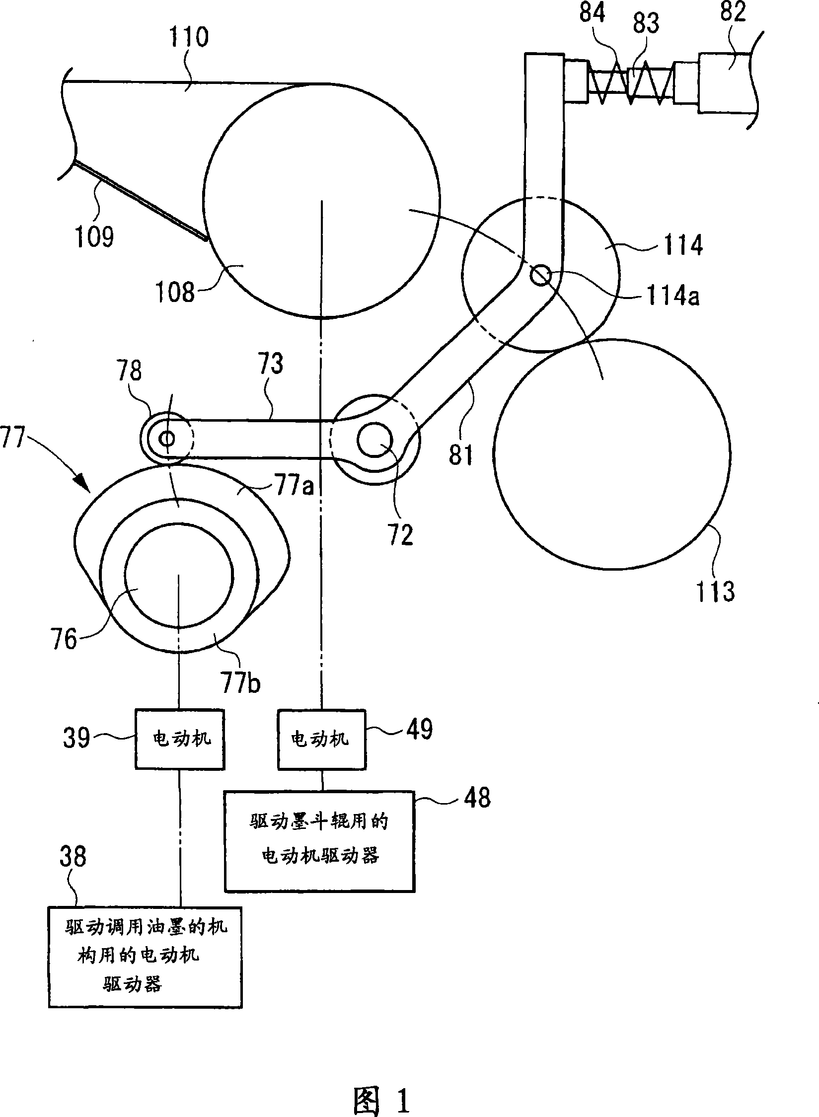
[0115] First, the configuration of the ink dispensing control device according to the first embodiment of the present invention will be described. Fig. 1 is a side view showing main parts of an ink unit of a printing machine according to a first embodiment of the present invention. In this figure, the same or equivalent components as those of the prior art in FIG. 48 described above are assigned the same reference numerals, and detailed description thereof will be omitted. Between the ink fountain roller 108 as the roller on the upstream side of the ink transfer direction and the agitating roller 113 as the roller on the downstream side of the ink transfer direction, the transfer roller 114 and the transfer shaft 72 that becomes the swing fulcrum for swinging are supported on the left and right sides. On the right frame (not shown in the figure), it can rotate freely. An axle end of this calling shaft 72 protrudes from the frame, and a cam lever 73 is provided on this protrud...

no. 2 approach

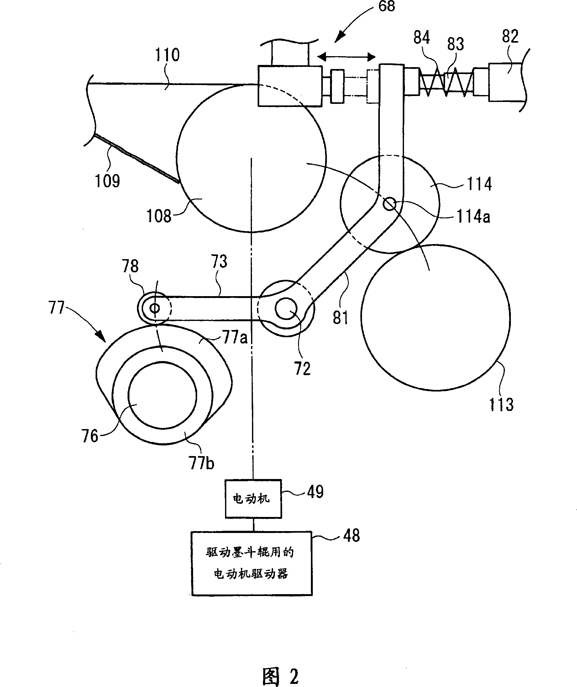
[0271]First, the configuration of an ink calling control device according to a second embodiment of the present invention will be described. Fig. 2 is a side view showing a main part of an ink unit of a printing machine according to a second embodiment of the present invention. In this figure, the same or equivalent components as those of the prior art in FIG. 48 described above are assigned the same reference numerals, and detailed description thereof will be omitted. In addition, in the second embodiment of the present invention, the basic drive of the ink dispensing mechanism is performed using the cam 77 and the like, but since the structure is the same as that of the first embodiment, description thereof will be omitted. In addition, the cam 77 is driven by the drive motor of the printing press. Between the ink fountain roller 108 as the roller on the upstream side of the ink transfer direction and the agitating roller 113 as the roller on the downstream side of the ink ...

no. 3 approach

[0418]First, the configuration of an ink dispensing control device according to a third embodiment of the present invention will be described. Fig. 2 is a side view showing main parts of an ink unit of a printing machine according to a third embodiment of the present invention. In this figure, the same or equivalent components as those of the prior art in FIG. 48 described above are assigned the same reference numerals, and detailed description thereof will be omitted. In addition, in the third embodiment of the present invention, the basic drive of the ink dispensing mechanism is performed using the cam 77 and the like, but since the structure is the same as that of the first embodiment, description thereof will be omitted. In addition, the cam 77 is driven by the drive motor of the printing press. Between the ink fountain roller 108, which is a roller on the upstream side in the ink transfer direction, and the stirring roller 113, which is a roller on the downstream side in...


PUM


Abstract

The present invention provides an ink feed control method and ink feed control apparatus, to control ink feed frequency according to printing press chroma or ink film thickness. In the ink feed control method for a printing press in which ink, supplied to an ink fountain roller 108 from a gap between each ink fountain key 109 and the ink fountain roller 108 by the rotation of the ink fountain roller 108, is supplied to the printing plate by swing operation of an ink ductor roller 114, so that a print is eventually made on a print sheet with the ink supplied to the printing plate, the method including the steps of: measuring any one of the density and the ink film thickness of a first printing product made by the printing press; and controlling the number of times of the swing operation of the ink ductor roller 114 relative to the rotation of the printing press in accordance with the value of the measured one of the density and the ink film thickness of the first printing product.

Description

technical field [0001] The present invention relates to a method for controlling ink loading of a printing machine and a control device for ink loading. Background technique [0002] Printing presses have an inking unit for supplying ink to printing plates. Fig. 48 is a side view of main parts showing an ink unit 100 of a general printing machine. Next, such an ink unit will be described with reference to Fig. 48 . Reference numeral 101 is a printing plate cylinder pivotally supported on a pair of left and right frames omitted in the figure, and a printing plate is mounted on its peripheral surface. A pair of freely removable inking rollers 103 supported by levers on a pair of vibrating rollers 102 is in contact with the surface of the plate cylinder 101. Above the vibrating rollers 102, three agitating rollers 104 whose circumferential surfaces are in contact with each other are provided. [0003] The vibrating roller 105 is in contact with one of the stirring rollers 10...

Claims


Application Information

Patent Timeline
Patent Type & Authority Applications(China)
IPC IPC(8): B41F31/02B41F31/14B41F33/10
CPCB41F31/12B41F31/14B41F33/0045
Inventor 日下明广沼内裕光
Owner KOMORI CORP
Why Eureka
Try Eureka