Liftable v-ladder

A technology of a herringbone ladder and an elevator, which is applied in the direction of ladders, buildings, and building structures, and can solve the problems of small lifting height, small height adjustment range of a ladder or a ladder, and restrictions on the height of the ladder's application site. Convenient transportation and storage, small space occupation and convenient adjustment

Active Publication Date: 2008-05-07
冷鹭浩
View PDF3 Cites 6 Cited by
  • Summary
  • Abstract
  • Description
  • Claims
  • Application Information

AI Technical Summary

Problems solved by technology

The herringbone ladder is widely used as an independent ladder, but because the two fixed ladders can not be adjusted in the length direction, the herringbone ladder has the following disadvantages: it can only be used in places where the ground is level, and it can only be used in places where the ground is level, and it can only be used on steps or uneven places. The use of this ladder is greatly restricted
Although these several solutions all solve the shortcoming that the place of use is restricted by the ground, the height of the ladder or the ladder can be adjusted in a small range, but because the heightening ladders of these solutions can only be lifted downwards to be applied to the ladder. Or the ground is uneven, but it cannot be lifted upwards and protruded from the top of the fixed ladder, which makes the lifting height small, the height adjustment range of the whole ladder or the ladder is small, and the application place of the ladder is limited in height

Method used


Image

  • Liftable v-ladder
  • Liftable v-ladder
  • Liftable v-ladder

Examples


Embodiment 1

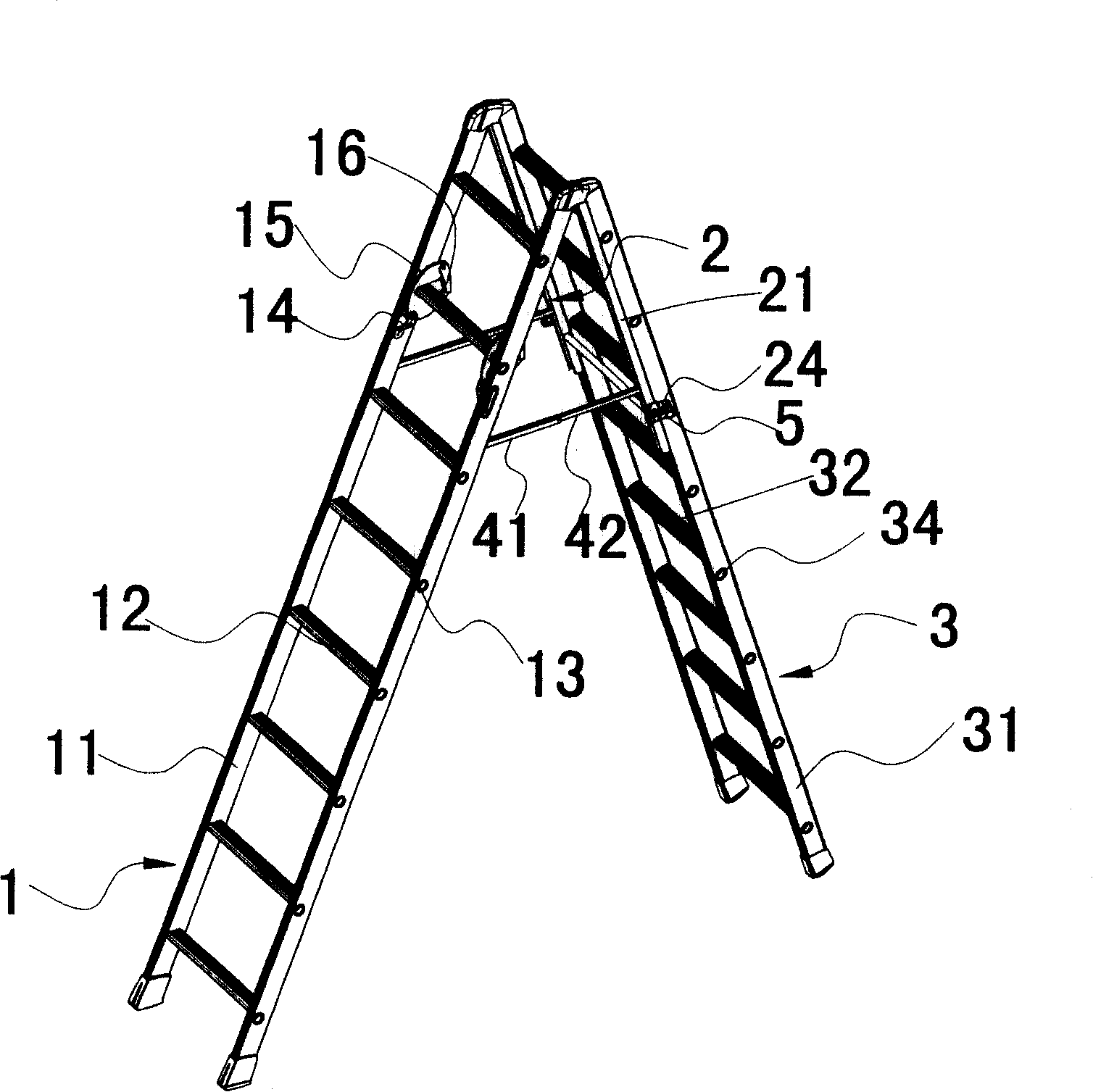
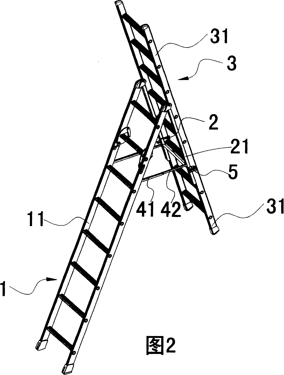
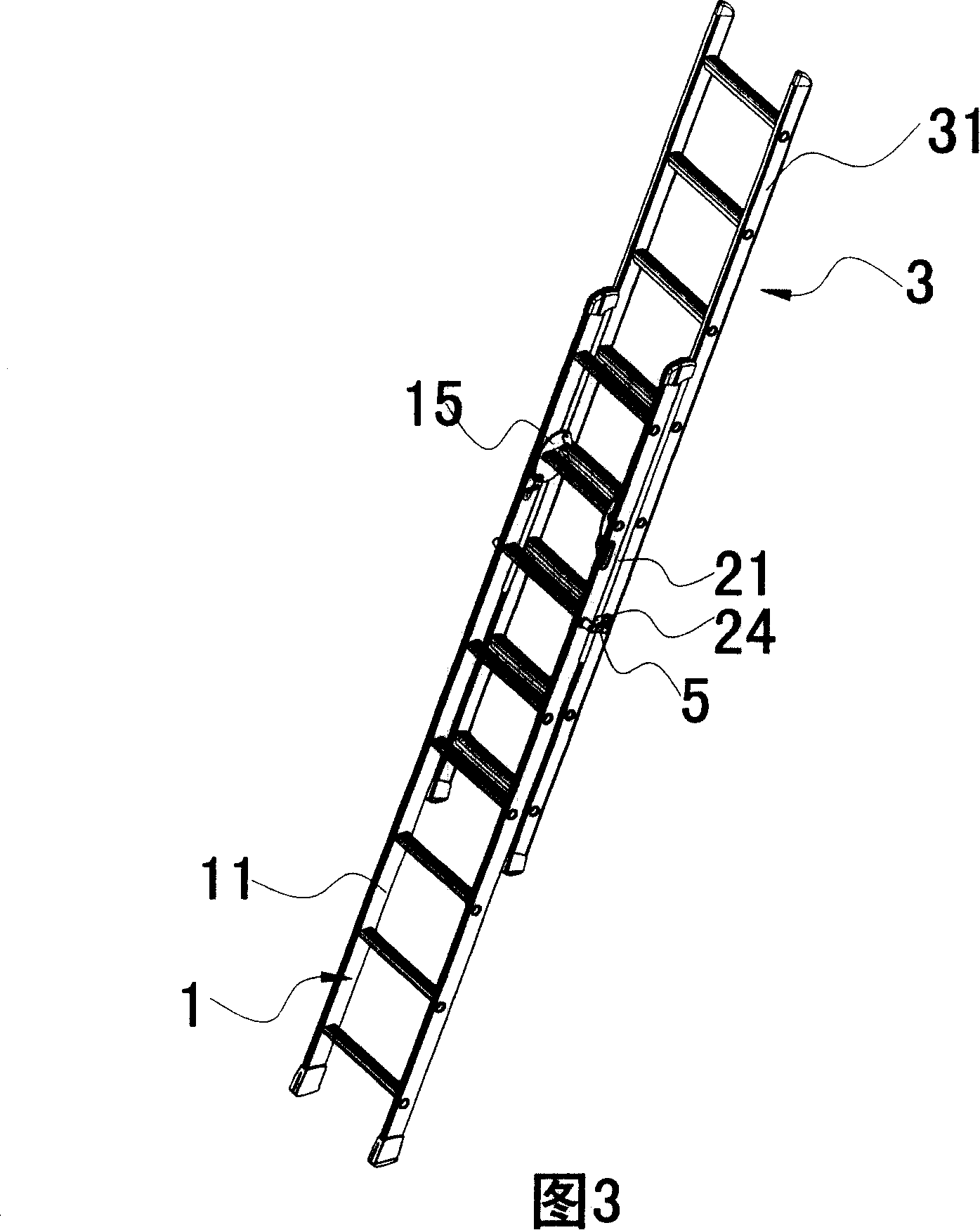
[0047] A liftable ladder, such as figure 1 , 2, 3, 4, 5, 6, and 7, including fixed ladder 1, transitional ladder 2 and lift 3, a rotatable connection is formed between the upper end of fixed ladder 1 and the upper end of transitional ladder 2, and the lift 2 and transitional ladder 3 constitute a connection that can slide up and down. Wherein, the length of the transition ladder 2 is about 1 / 3 of the length of the fixed ladder 1, and the length of the lift 3 is about equal to the length of the fixed ladder 1.

[0048] Such as figure 1 , 8 As shown, the fixed ladder 1 includes two parallel fixed leg pipes 11 and several pedals 12 fixed between the two fixed leg pipes 11, and these several pedals 12 are horizontally arranged; as Figure 11 As shown, the horizontal cross-section of the fixed leg pipe 11 is R-shaped. The fixed ladder 1 is provided with a plurality of second fixing holes 13, the second fixing holes 13 are evenly spaced up and down and the axes are in a horizont...

Embodiment 2

[0061] The difference between this embodiment and Embodiment 1 is that: as shown in Figure 20, the horizontal cross section of the fixed leg tube 11 is shaped like an R; the structure of the transition leg tube 21 is the same as that of the fixed leg tube 11, and the horizontal The cross section is also R-shaped, and the opening end of the R-shaped transition leg tube 21 forms a chute 23; the lifting leg tube 31 is shaped like a mouth, and the lifting leg tube 31 forms a slide rail. The lifting leg pipe 31 is slidably connected in the slide groove 23 .

Embodiment 3

[0063] The difference between this embodiment and Embodiment 1 is that: as shown in Figure 21, the horizontal cross section of the fixed leg tube 11 is shaped like a mouth; the horizontal cross section of the transition leg tube 21 includes a mouth part and a U-shaped part , wherein the sides of the U-shaped part coincide with the sides of the U-shaped part, and the opening of the U-shaped part shrinks inward, so that the inside of the U-shaped part forms a chute 23; the lifting leg tube 31 is shaped like a mouth, and the Lifting leg pipe 31 becomes slide rail. The lifting leg pipe 31 is slidably connected in the slide groove 23 .


PUM


Abstract

The invention discloses a liftable herringbone ladder, which comprises a fixed ladder, a transitional ladder and an elevator. A rotatable connection is formed between the upper end of the fixed ladder and the upper end of the transitional ladder, and a vertical sliding connection is formed between the elevator and the transitional ladder; Wherein, the fixed ladder and the transitional ladder can be opened and positioned to form a herringbone ladder or folded and positioned to form a straight ladder. The end protrudes from the bottom end of the transitional ladder. This technical solution has the following advantages: the elevator slides relative to the transitional ladder so that its top end protrudes from the transitional ladder top or/and its bottom end protrudes from the transitional ladder bottom, which can improve the entire herringbone ladder or one-character ladder. The height of the ladder can make the herringbone ladder suitable for various places even if the ground of the place is uneven or is a ladder, the ladder has a variety of adjustment functions for the elevator and the ladder height adjustment range is large.

Description

technical field [0001] The invention relates to an independent ladder, in particular to a liftable ladder. Background technique [0002] Early herringbone ladders consisted of two fixed ladders and a positioning device between the two fixed ladders. The tops of the two fixed ladders formed a rotatable connection, and the two fixed ladders could be opened and positioned to form a herringbone ladder or folded Position to form a ladder. The herringbone ladder is widely used as an independent ladder, but because the two fixed ladders can not be adjusted in the length direction, the herringbone ladder has the following disadvantages: it can only be used in places where the ground is level, and it can only be used in places where the ground is level, and it can only be used on steps or uneven places. The use of this herringbone ladder is just restricted greatly. [0003] Someone has proposed a solution for the above-mentioned shortcomings: the herringbone ladder includes two fix...

Claims


Application Information

Patent Timeline
Patent Type & Authority Applications(China)
IPC IPC(8): E06C1/30E06C7/02
CPCE06C7/06E06C1/18E06C1/12E06C1/22
Inventor 冷鹭浩
Owner 冷鹭浩
Why Eureka
Try Eureka