Connection device

一种连接装置、接合头的技术,应用在连接构件、服饰、扣件等方向,能够解决不具有外观、难以消除摩擦噪音、组装麻烦等问题,达到良好外观、可靠组装、避免变形的效果

Inactive Publication Date: 2008-05-07
YKK CORP
View PDF3 Cites 8 Cited by
  • Summary
  • Abstract
  • Description
  • Claims
  • Application Information

AI Technical Summary

Problems solved by technology

However, since the large-diameter hole is not formed as in JP-Y-No. 62-27701, it is cumbersome to assemble the three components and does not have a good appearance.
Although the annular opening is provided mainly for shock absorption, unless any special operation is performed, it is difficult to eliminate the gap between the metal and the elastic material such as rubber when the metal rotatable hook body is rotated relative to the strap holder. harsh friction noise

Method used


Image

  • Connection device
  • Connection device
  • Connection device

Examples


no. 1 example

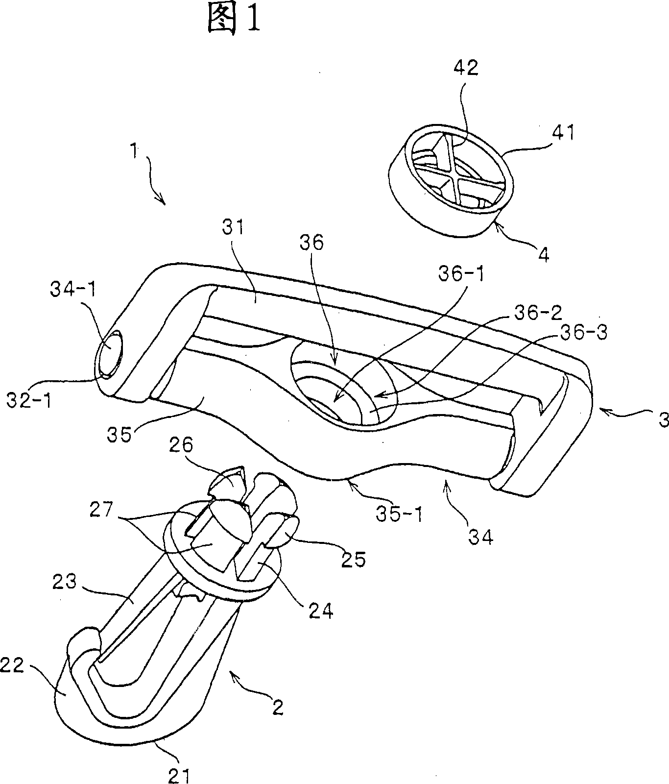
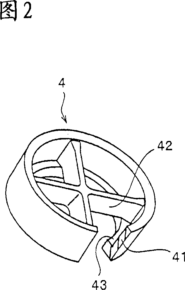
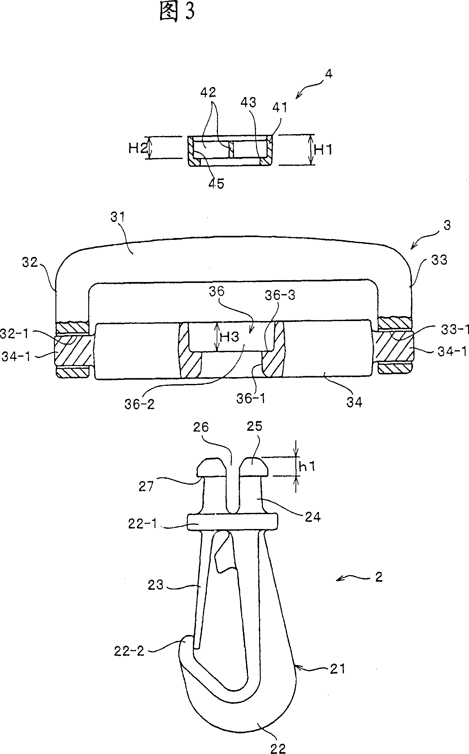
[0025] FIG. 1 is a perspective view of a rotatable hook as a representative example of a connecting device according to a first embodiment of the present invention, in which various parts of the rotatable hook are disassembled. Fig. 2 is an enlarged perspective view partially cut away showing a ring member of the rotatable hook. Figure 3 is an enlarged front view, partly broken away, of the various components of the rotatable hook. Fig. 4 is a partially cutaway front view showing main parts of the assembled rotatable hook. Fig. 5 is a cross-sectional view along line V-V in Fig. 4 . In the following description, the direction from the engaging head 25 to the hook portion 22 in the rotatable hook body 2 shown in FIG.

[0026] The rotatable hook 1 of the present invention includes a rotatable hook main body 2 as a connecting device main body, a belt fixing member 3 fixed to one end of a belt or the like, and a ring member 4 . The strap fixing part 3 is rotatably connected with...

no. 2 example

[0042] Next, the buckle 5 as the connecting means of the second embodiment of the present invention will be described. In the description of the second embodiment described below, the same reference numerals and names are used to denote components having the same structure as that of the first embodiment. Therefore, detailed descriptions of these components are omitted. Here, FIG. 6 is a perspective view showing the buckle 5 of the second embodiment.

[0043] The buckle 5 of the second embodiment includes a buckle main body 50 having a male piece 51 and a female piece 54 engaged with the male piece 51 , and the belt holder 3 rotatably supported by the buckle main body 50 . The female piece 54 has a neck 24 and a joint head 25 which expands in an outward direction from the center of the axis so as to be able to reduce the diameter of the joint head 25 at the front end of the neck 24 . The male piece 51 is inserted into the female piece body 55 on the opposite side of the enga...


PUM


Abstract

A connecting device which has an excellent appearance, produces no frictional sound between a connecting device main body such as a swivel hook main body and a belt attaching member and can be assembled easily and securely. The connecting device includes a neck portion (24) standing from a proximal portion (22-1) of a main body (2, 50) of the connecting device (1, 5) and an engagement head (25) which is expanded in an outward direction form a center of an axis line such that a diameter thereof can be reduced, the engagement head being provided at a front end of the neck portion (24). A belt attaching member is connected to the main body rotatably around the neck portion. A through hole which the engagement head can be engaged with by insertion is formed in part of the belt attaching member. In the through hole, a small-diameter hole portion having a smaller diameter than the diameter of the engagement head and a large-diameter hole portion having a large diameter than the diameter of the engagement head are connected via a stepped portion. The large-diameter hole portion has a ring-like member which allows the neck portion to be inserted therethrough. The ring-like member has a cylindrical wall portion which is accommodated in the large-diameter hole portion and a ring-like engaging portion provided at an end of the wall portion and extended toward a center thereof. An inside diameter of the engaging portion (43) is equal to an outside diameter of the diameter of the engagement head (25) when it is reduced.

Description

technical field [0001] The present invention relates to a connecting device such as a rotatable hook made of synthetic resin or a buckle made of synthetic resin for connecting or separating two ends of a strap or two straps, wherein the rotatable The swivel hook can be easily connected with the locking element fixed on the bag (such as shoulder bag or backpack) by hooking, and the present invention more particularly relates to a connecting device in which the belt fixing part and the connecting device main body can rotate relative to each other. Background technique [0002] Conventionally, for example, as disclosed in Japanese Utility Model Laid-Open Document (JP-Y) No. 62-27701 and U.S. Patent No. 6,286,190, a rotatable hook (wherein the hook shape can be The main body of the swivel hook and the strap fixing piece are rotatably connected to each other) and put into practical use. [0003] The rotatable hook in JP-Y-No. 62-27701 has a rotatable hook main body and a ribbon ...

Claims


Application Information

Patent Timeline
Patent Type & Authority Applications(China)
IPC IPC(8): F16B45/02
CPCF16B21/088F16B45/02F16G15/08A44B11/266A44B11/28Y10T24/45419Y10T24/45241Y10T24/4755Y10T24/47Y10T24/45581F16B45/036
Inventor 上原亮一郎
Owner YKK CORP
Why Eureka
Try Eureka