Device for examining the end position of displaceable parts of a rail switch

A technology of terminal position and moving parts, applied in the direction of locking mechanism for turnout, track, railway car body parts, etc., to achieve the effect of compact structure

Inactive Publication Date: 2008-05-07
VAE火车系统有限责任公司 +1
View PDF8 Cites 6 Cited by
  • Summary
  • Abstract
  • Description
  • Claims
  • Application Information

AI Technical Summary

Problems solved by technology

However, a disadvantage of such a device is that it is extremely difficult to adapt the end position detection device to the different switching lifts, that is, this adaptation

Method used


Image

  • Device for examining the end position of displaceable parts of a rail switch
  • Device for examining the end position of displaceable parts of a rail switch
  • Device for examining the end position of displaceable parts of a rail switch

Examples


Embodiment Construction

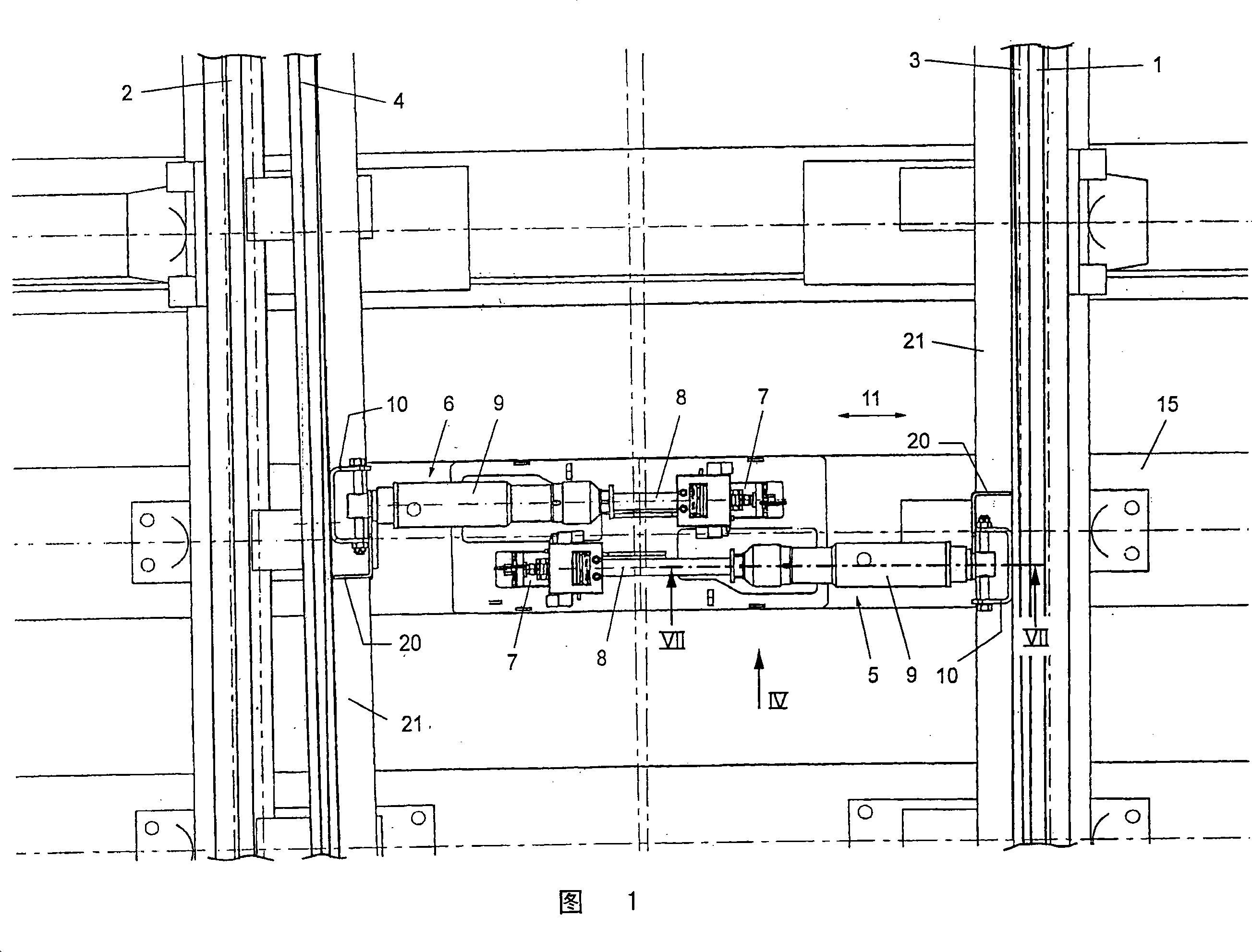
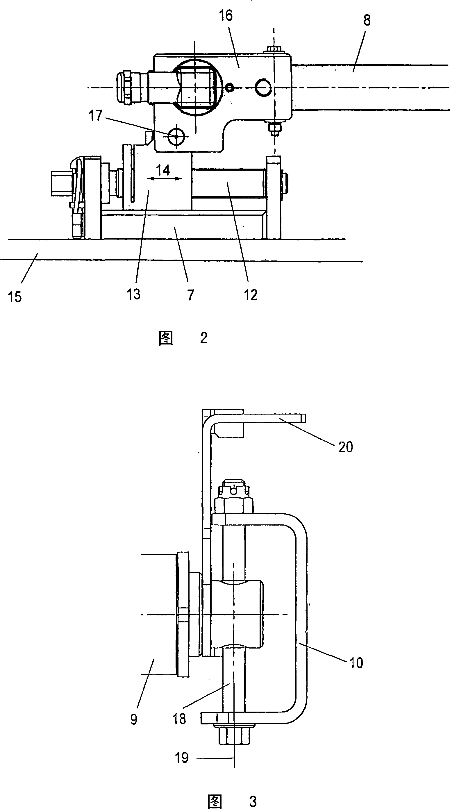
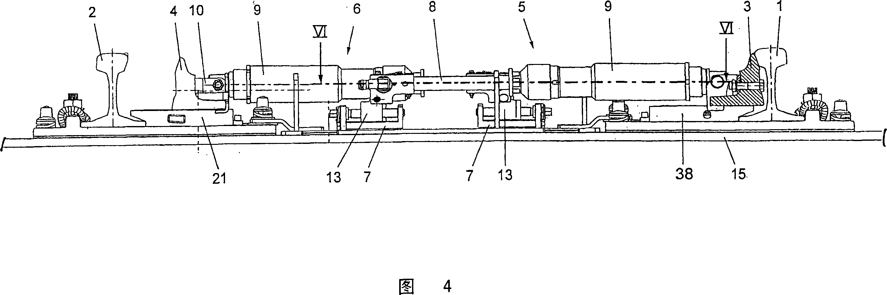
[0022] FIG. 1 shows a section of a rail switch with jaw rails 1 and 2 and switch rails 3 and 4 . The switch rail 3 abuts against the jaw rail 1 , while the switch rail 4 moves away from the jaw rail 2 . Separate end position detection devices 5 and 6 are assigned to the switch rails 3 and 4 , so that a complete mechanical end connection of the switch rails 3 and 4 is achieved. The terminal position detection devices 5 and 6 are respectively fixed on the sleeper 15 through the bearing housing 7 . The end position detection devices each comprise a connecting rod 8 which is sealingly inserted into a tubular housing 9, wherein the tube 9 is connected via a hinged fork 10 to the tongue rail 3 or Say 4 on. When switching the switch according to the double arrow 11, the pipe 9 connected to the switch rail is carried along with it and moves relative to the connecting rod 8, wherein as will be explained below according to the relative position of the pipe 9 The relative displacement...


PUM


Abstract

The invention relates to a device for checking the end positions of movable parts of a track switch, wherein at least one individual end position detection device (5, 6) is assigned to each movable switch part (3, 4), wherein the The terminal position detection device (5, 6) comprises a connecting rod (8) and a detection device housing (9), and the connecting rod (8) is inserted into the detection device housing (9) and in the detection device housing (9) At least one end position switch (5, 6) is arranged for detecting two end positions of the movable switch element (3, 4). According to the invention, the connecting rod ( 8 ) in the region where it is inserted into the housing ( 9 ) or the housing ( 9 ) has at least two shafts spaced from one another in the axial direction for actuating the at least Switch sides of an end position switch (5, 6), wherein at least one of the switch sides is arranged in such a way that it can be adjusted in the axial direction relative to the other switch side and fixed in a corresponding position.

Description

technical field [0001] The invention relates to a device for checking the end positions of movable parts of a rail switch, wherein at least one individual end position detection device is assigned to each movable part of the track switch, wherein the end position detection device comprises a Connecting rod and a detection device housing into which the connecting rod is inserted and in which at least one end position for detecting two end positions of the movable switch element is arranged switch. Background technique [0002] Adjusting devices for movable point rails, in particular switch rails or movable points, which are provided with end position detection devices are generally known from the prior art. In the known adjusting device, the movable switch element is mechanically shifted by means of an electric or hydraulic switch drive, wherein a separate or integrated switch is provided in addition to the switch drive. The locking device in the drive unit and, in any case...

Claims


Application Information

Patent Timeline
IPC IPC(8): B61L5/10E01B7/22
CPCB61L5/107E01B7/20
Inventor H·阿克莱特纳M·米埃尔格W·奥伯霍夫纳
Owner VAE火车系统有限责任公司
Why Eureka
Try Eureka