Laser cutting machine tool and cutting head for laser cutting machine tool

A laser cutting machine and cutting head technology, applied in laser welding equipment, welding equipment, metal processing equipment, etc., can solve the problems that the focusing lens is easy to burn, the cutting head is not equipped with a cooling device, and the relative distance cannot be detected.

Inactive Publication Date: 2008-05-14
HANS LASER TECH IND GRP CO LTD
View PDF0 Cites 20 Cited by
  • Summary
  • Abstract
  • Description
  • Claims
  • Application Information

AI Technical Summary

Problems solved by technology

[0003] In order to solve the technical problem that the laser cutting machine in the prior art cannot detect the relative distance between the focal point of the focusing lens and the workpiece to be cut
In addition, the present invention further solves the technical problem that there is no cooling device in the existing cutting head, and the focusing lens is easily burned

Method used


Image

  • Laser cutting machine tool and cutting head for laser cutting machine tool
  • Laser cutting machine tool and cutting head for laser cutting machine tool
  • Laser cutting machine tool and cutting head for laser cutting machine tool

Examples


Embodiment Construction

[0018] The present invention will be described in detail below in conjunction with the accompanying drawings and embodiments.

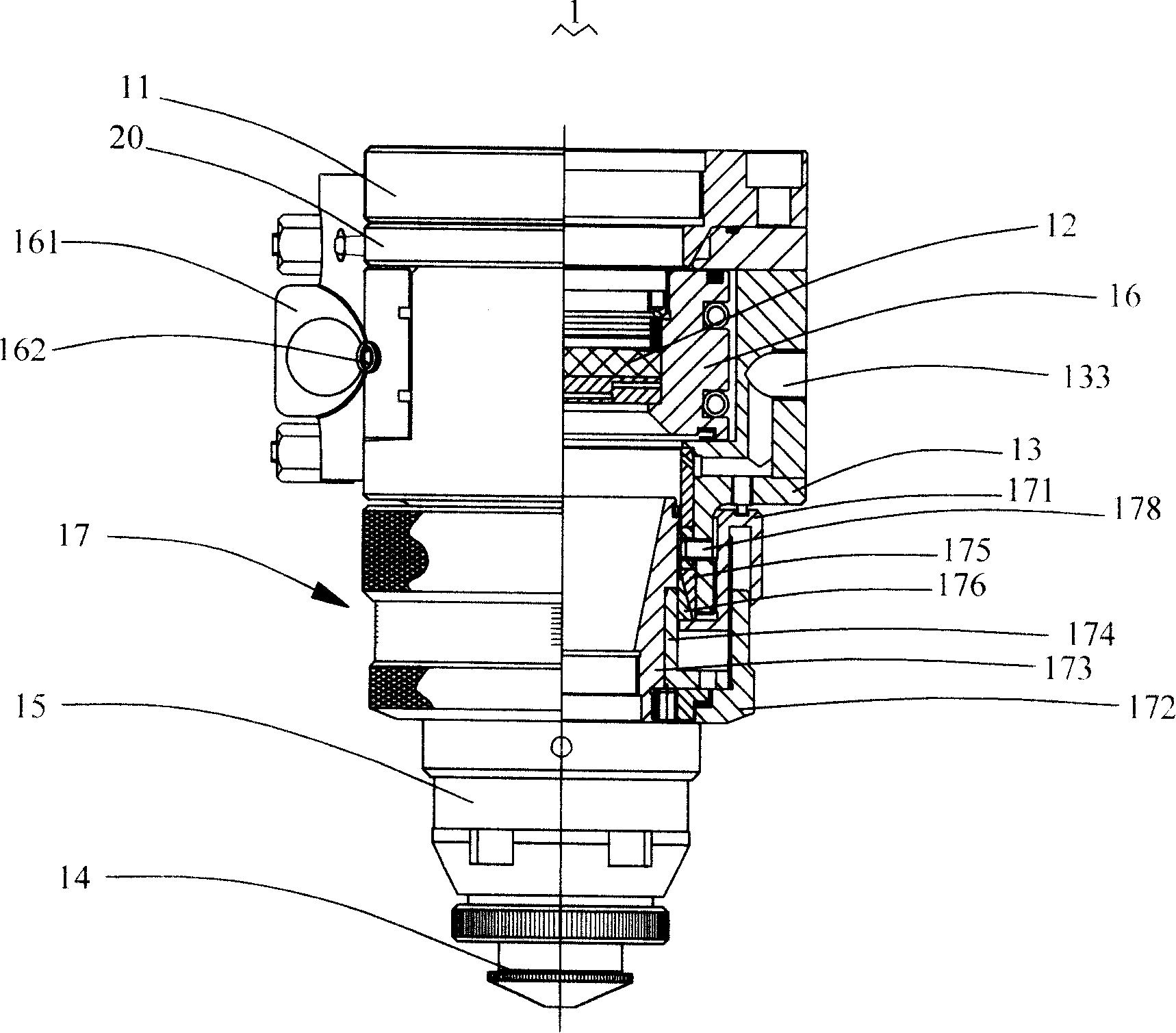
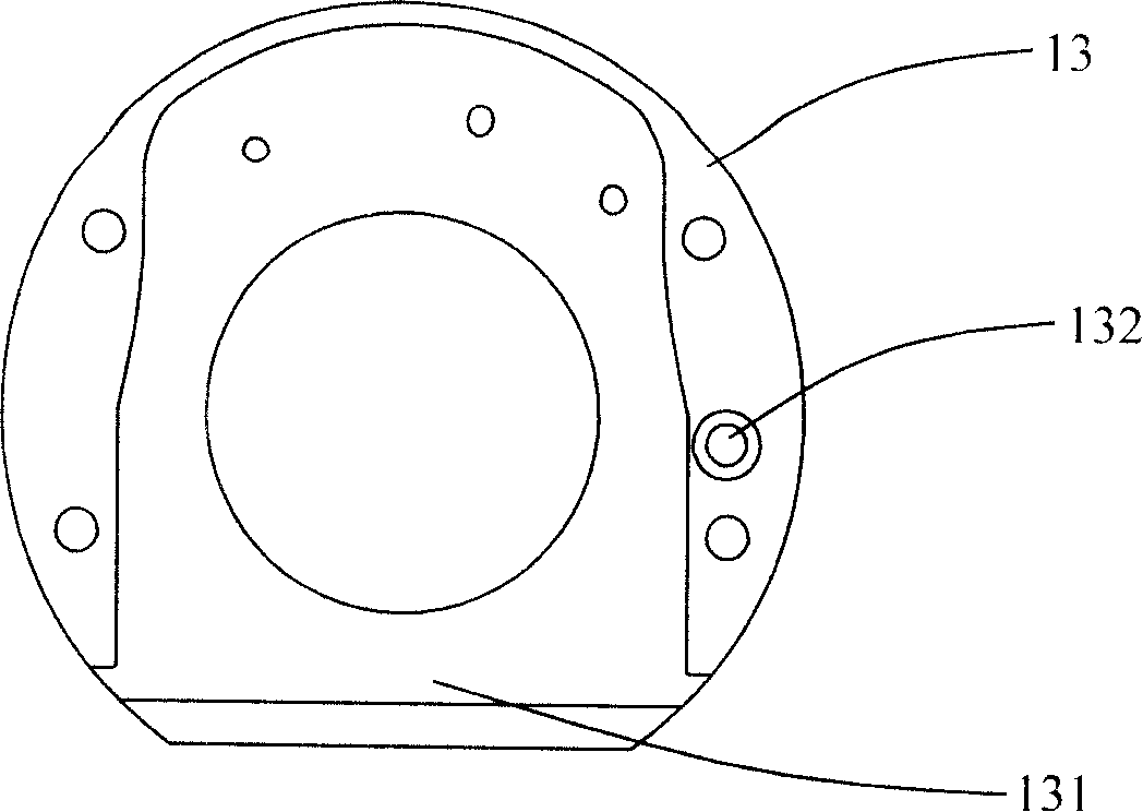
[0019] Such as Figure 1-Figure 3 As shown, the cutting head 1 for laser cutting machine of the present invention is basically a hollow cylindrical structure, which includes a connecting mechanism 11 for connecting to a servo transmission mechanism (not shown) of a laser cutting machine, and a connecting mechanism 11 for connecting with the connecting mechanism 11. The mirror cavity box 13 containing the focusing lens 12 and the cutting nozzle 14 connected with the mirror cavity box 13 are used. In this embodiment, the cutting head 1 is further provided with a capacitive sensor 15 for sensing the capacitance between the cutting nozzle 14 and the workpiece to be cut (not shown).

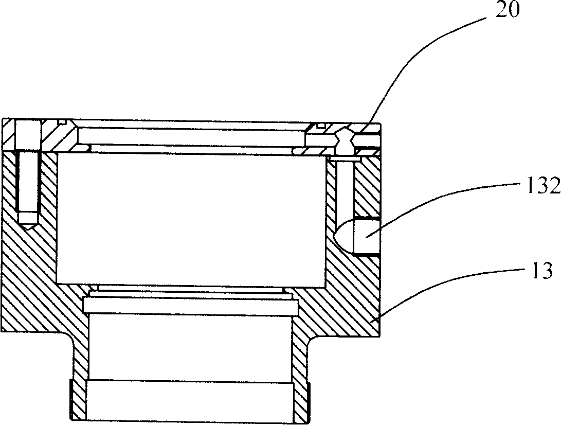
[0020] In this embodiment, the connecting mechanism 11 is a connecting flange, which is connected to the Z-axis pallet of the laser cutting machine. A sealing ring 20 is pr...


PUM


Abstract

The invention relates to a laser cutting machine and a cutting head for the laser cutting machine; wherein, the cutting head comprises a binding mechanism for servo transmission mechanism used to connect the laser cutting machine, a mirror cavity box connected with the binding mechanism used to accommodate the focusing lens, and a cutting mouth connected with the mirror cavity box; the cutting head also comprises a capacitance sensor inducted the capacitance value between the cutting head and cutting workpiece. With the structure, the invention has the advantages of utilizing the capacitance value of the plate capacitor composed of a capacitance sensor induction cutting mouth and a cut workpiece, and controling the servo transmission mechanism of the cutting machine based on the capacitance value, thus the follow-up of the cutting mouth (lens focal point) with respect to the cut workpiece is achieved.

Description

【Technical field】 [0001] The present invention relates to a laser cutting machine, more particularly to a cutting head for the laser cutting machine. 【Background technique】 [0002] In recent years, laser cutting machines have been widely used in the cutting process of various materials, but the structure of the cutting head used by existing laser cutting machines is relatively simple. During the cutting process, it is impossible to detect the relative distance between the focal point of the focusing lens and the workpiece to be cut. As a result, when the material to be cut has a large format or has undulating surfaces, the surface quality of the cut is poor, the cutting speed is low, and even the cutting cannot be done at all. In addition, there is no cooling device in the existing cutting head, and the focusing lens is easily burned due to overheating. 【Content of invention】 [0003] In order to solve the technical problem that the laser cutting machine in the prior art...

Claims


Application Information

Patent Timeline
IPC IPC(8): B23K26/00B23K26/42B23K26/08B23K26/04B23K26/14B23K26/38B23K26/70
Inventor 高云峰蔡建平吴小华
Owner HANS LASER TECH IND GRP CO LTD
Why Eureka
Try Eureka