Self-temperature controlled valve

A technology of self-operated temperature control valve and valve cover, which is applied in the direction of lifting valve, valve details, valve device, etc., and can solve the problems of wear gap, water leakage, heat medium leakage, etc.

Inactive Publication Date: 2008-05-14
北京菁华资源科技有限公司
View PDF0 Cites 22 Cited by
  • Summary
  • Abstract
  • Description
  • Claims
  • Application Information

AI Technical Summary

Problems solved by technology

However, since the temperature sensitive element is always changing with the temperature, it drives the piston to move continuously. After a long time, due to the continuous friction between the piston rod and the seal, there will be wear gaps, which will eventually lead to the leakage of the heat medium. leak
For example, after installing this kind of temperature control valve in a certain area, a large area of ​​water leakage occurred in less than a year, which was caused by this structural defect.

Method used


Image

  • Self-temperature controlled valve

Examples


Embodiment Construction

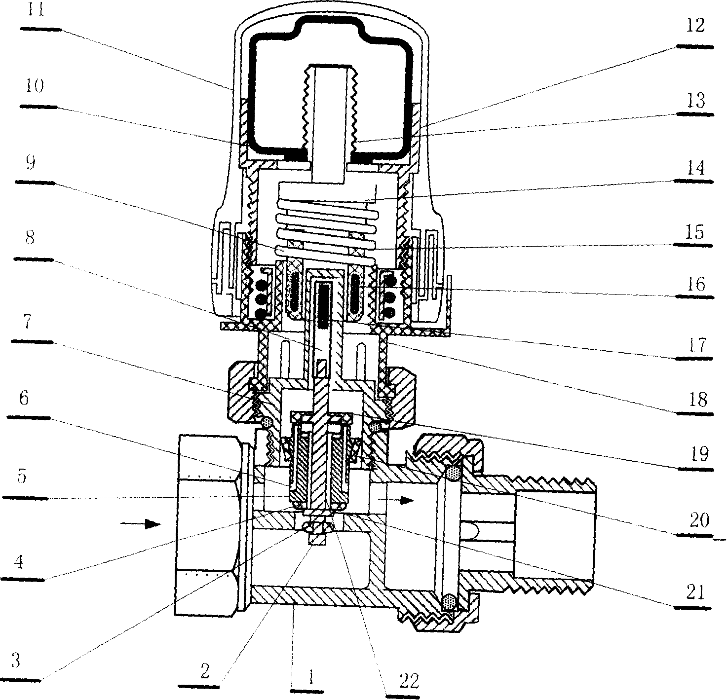
[0008] The temperature sensitive element of this embodiment adopts the structure of a liquid temperature bulb and a bellows. The entire structural composition is shown in the drawings and descriptions. Embodiments are now described in conjunction with the accompanying drawings.

[0009] On the upper part of the valve body (1) that enters and exits from the bottom, there is a valve cover (7) with a sleeve. In the inner cavity of the valve cover (7), there is a self-operated valve core and valve stem. The valve core is composed of upper and lower sealing rings. (4), composed of piston rod (5); valve stem is composed of upper valve stem (8), lower valve stem (2), magnetic column (17), rubber sleeve (3); upper valve stem (8) is on the valve cover (7) The inner cavity is inserted into the casing; the valve cover (7) outside the casing is covered with a circular sleeve (15) that can move up and down outside the casing, and a magnetic ring (16) is embedded in the circular sleeve (15...


PUM


Abstract

The upper part of a valve body without mechanical external communication or mechanical abrasion is provided with a valve cover with a sleeve; an internal cavity of the valve cover is provided with a self-operated valve core and a valve rod; the valve rod is inserted into a sleeve in the valve cover in the valve cavity; the upper end of the valve rod is internally provided with a magnetic column; the external surface of the valve cover sleeve is sleeved with a round sleeve which can move up and down out of the sleeve; the round sleeve is internally provided with a magnetic ring which can move up and down; the valve rod can also move up and down driven by the magnetic column; the external surface of the round sleeve is sleeved with a recovery spring; a transmission rod is supported by the upper part of the round sleeve; the top part of the transmission rod is connected with a temperature thermal sensitive element; a piston column is arranged in the valve core; the interior of the piston column is provided with a pressure release hole; an upper opening of the pressure release hole is communicated with the upper space of the valve cover and can be covered by the sealing cover on the valve rod; an opening at the lower side surface is communicated with a water inlet of the valve body.

Description

technical field [0001] A self-operated temperature control valve for a radiator belongs to the technical field of civil heating equipment. technical background [0002] In recent years, with the deepening of the country's reform of the welfare heating policy, it has become the general trend to implement household accounting and install automatic temperature control valves on radiators for heating systems. However, the existing automatic temperature control valve technology, whether domestic or foreign, uses temperature sensitive elements to directly drive the piston to move up and down to control the opening and closing of the valve, thereby achieving the purpose of controlling the indoor temperature. However, since the temperature sensitive element is always changing with the temperature, it drives the piston to move continuously. After a long time, due to the continuous friction between the piston rod and the seal, there will be wear gaps, which will eventually lead to the...

Claims


Application Information

Patent Timeline
Patent Type & Authority Applications(China)
IPC IPC(8): F16K1/00F16K31/08F16K31/64
Inventor 全龙浩董民超
Owner 北京菁华资源科技有限公司
Why Eureka
Try Eureka