
Decompression drying device

A decompression drying device and drying technology, which are used in transportation and packaging, conveyor objects, optics, etc., can solve problems such as conflict or damage, substrate position deviation, etc., and achieve the effect of efficient, safe and smooth moving in and out

Inactive Publication Date: 2011-04-27
TOKYO ELECTRON LTD
View PDF1 Cites 0 Cited by
  • Summary
  • Abstract
  • Description
  • Claims
  • Application Information

AI Technical Summary

Problems solved by technology

[0005] As mentioned above, the conventional reduced-pressure drying apparatus needs to move the upper chamber up and down (open and close) every time the substrate is carried in and out of the chamber. Many bad things happen in
That is, if the size of the substrate is more than 2m on one side like the LCD substrate, the chamber will also be significantly enlarged, and only the upper chamber will weigh more than 2 tons, so a large lifting mechanism is required. Dust generation problems and worker safety issues caused by large vibrations become apparent
In addition, transport machinery and equipment have become larger and larger, but it is difficult to hold and transport large substrates horizontally, and the substrate after resist coating is transported in a curved state like a large fan, so it is easy to cause pressure reduction. Problems such as displacement, collision, or damage of substrates in the chamber of the drying device when they are moved in and out or loaded / unloaded

Method used


Image

  • Decompression drying device
  • Decompression drying device
  • Decompression drying device

Examples


Embodiment Construction

[0054] Hereinafter, preferred embodiments of the present invention will be described with reference to the drawings.

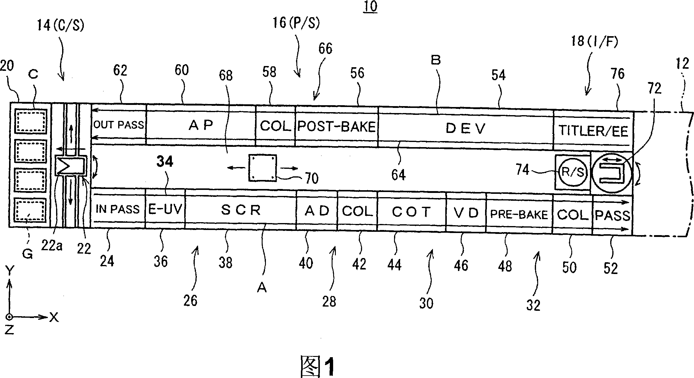
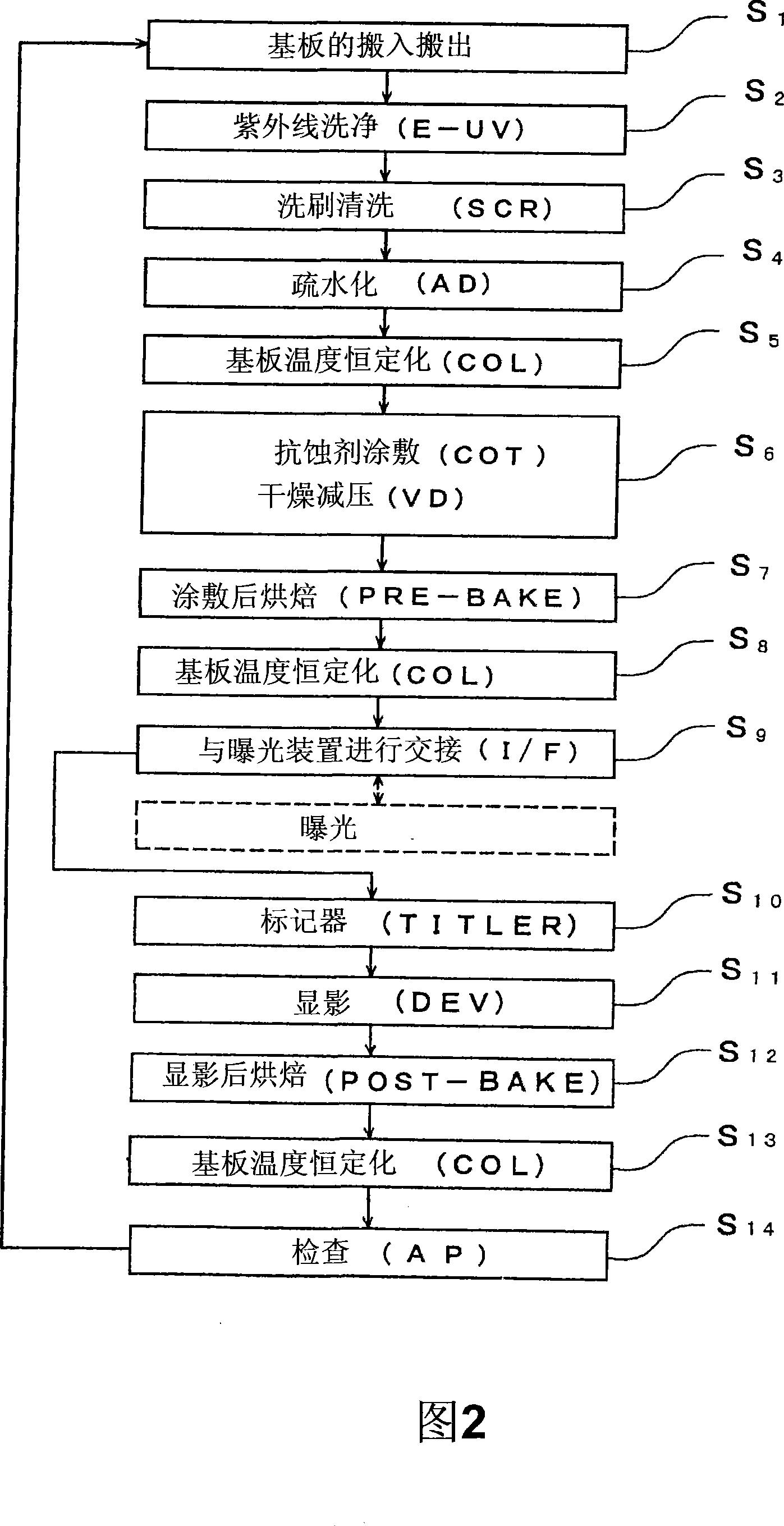
[0055] FIG. 1 shows a coating and developing treatment system as one configuration example of a reduced-pressure drying apparatus applicable to the present invention. The coating and development processing system 10 is set in a clean room, for example, with a glass substrate as the substrate to be processed, cleaning, resist coating, pre-baking, developing and post-baking, etc. in the photolithography process are performed in the LCD manufacturing process. series processing. Exposure processing is performed in an external exposure device 12 provided adjacent to the system.

[0056] The coating and developing processing system 10 is provided with a horizontally long process station (process position) (P / S) 16 at the center, and cassette stations (cassette position) (C / S) at both ends in the longitudinal direction (X direction). ) 14 and interface station (inter...


PUM

PropertyMeasurementUnit
diameteraaaaaaaaaa
diameteraaaaaaaaaa

Abstract

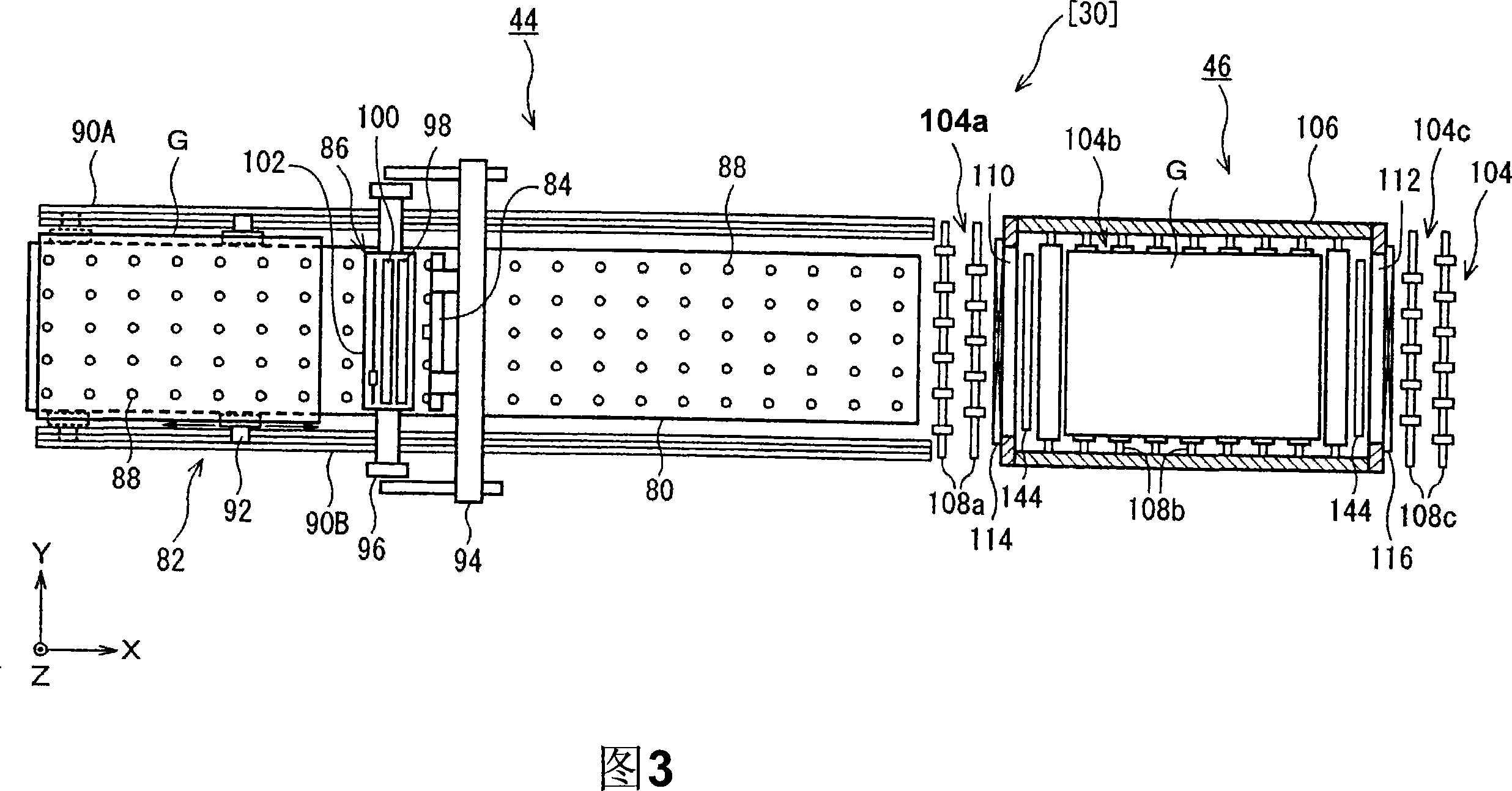
The invention provides a pressure-reduction drying device which achieves the transportation in and out of a processed substrate effectively, safely and stably and restrains the transfer-printing trace adhered on the substrate contact part of a coating film of the substrate minimally. The pressure-reduction drying device (VD) (46) roll-transports the substrate G to be pressure-reduced and dried into a cavity (106) through the roll-transportation carried out on a transportation-in side roll-transportation channel (104a) and an inner roll-transportation channel (104b); and transports the substrate G which is pressure-reduced and dried out from the cavity (106) through the roll-transportation carried out on an inner roll-transportation channel (104b) and a transportation-out side roll-transportation channel (104c). During the pressure-reduction drying process, the substrate G is maintained in a horizontal state and lifted upwards from the inner roll-transportation channel (104b) through aplurality of lifting pins (128), and the substrate G is supported by the superfine pin tip part of the lifting pin.

Description

technical field [0001] The present invention relates to a reduced-pressure drying device for drying a coating liquid coated on a substrate to be processed under reduced pressure. Background technique [0002] For example, in the photolithography process of flat panel display (FPD) manufacturing such as liquid crystal display (LCD), this kind of reduced pressure drying device is used for pre-preparing the resist solution coated on the substrate to be processed (glass substrate, etc.). Baked and allowed to dry. [0003] For example, as described in Patent Document 1, the decompression drying device of the prior art includes: a lower chamber of a bracket or a shallow container type with an upper opening; The lid-shaped upper chamber formed by fitting. A stage (stage) is arranged in the lower chamber, and after the substrate is horizontally placed on the stage, the chamber is closed (the upper chamber is brought into close contact with the lower chamber), and a reduced-pressur...

Claims


Application Information

Patent Timeline
Patent Type & Authority Patents(China)
IPC IPC(8): G03F7/38H01L21/00H01L21/677
CPCG02F1/13G03F7/70858H01L21/67207H01L21/68742
Inventor 坂本贵浩坂井光广八寻俊一
Owner TOKYO ELECTRON LTD
Learn More