
Wafer processing tape

a processing tape and wafer technology, applied in the direction of film/foil adhesives, layered products, transportation and packaging, etc., can solve the problems of difficult suppression of transfer marks, troublesome actual use of tapes, and problems in semiconductor wafer processing, so as to reduce voids, reduce voids, and suppress transfer marks on the adhesive layer

Active Publication Date: 2012-04-26
FURUKAWA ELECTRIC CO LTD
View PDF4 Cites 6 Cited by
  • Summary
  • Abstract
  • Description
  • Claims
  • Application Information

AI Technical Summary

Benefits of technology

[0016]An object of the present invention is to provide a wafer processing tape capable of sufficiently suppressing the transfer marks on an adhesive layer when the wafer processing tape having an adhesive layer and a pressure-sensitive adhesive film formed on a release film is wound in a roll shape. Further, the wafer processing tape is capable of suppressing voids caused by a change in a temperature.
[0031]According to the present invention, the wafer processing tape includes the colored support member formed on a front surface or a backside surface of the release film, thereby suppressing the transfer marks on the adhesive layer. Further, it is possible to clearly recognize a type of a dicing die bonding tape.

Problems solved by technology

The formation of the transfer marks is remarkably increased especially when the adhesive layer 52 is formed of a soft resin and has a relatively large thickness or the dicing die bonding tape 50 is wound in a large number of times. When the transfer marks are formed, an adhesion defect occurs between the adhesive layer 52 and the semiconductor wafer, thereby causing a problem in the semiconductor wafer process.
Accordingly, it is difficult to set the product on a tape mounter, thereby causing a trouble in an actual use of the tape.
Accordingly, the support layer has a limited width, and a relatively narrow width relative to outer diameters of the adhesive layer and the pressure-sensitive adhesive film, thereby making it difficult to suppress the transfer marks.

Method used


Image

  • Wafer processing tape
  • Wafer processing tape
  • Wafer processing tape

Examples


first embodiment

[0051]An explanation of a wafer processing tape according to a first embodiment of the present invention will be explained in detail with reference to the attached drawings.

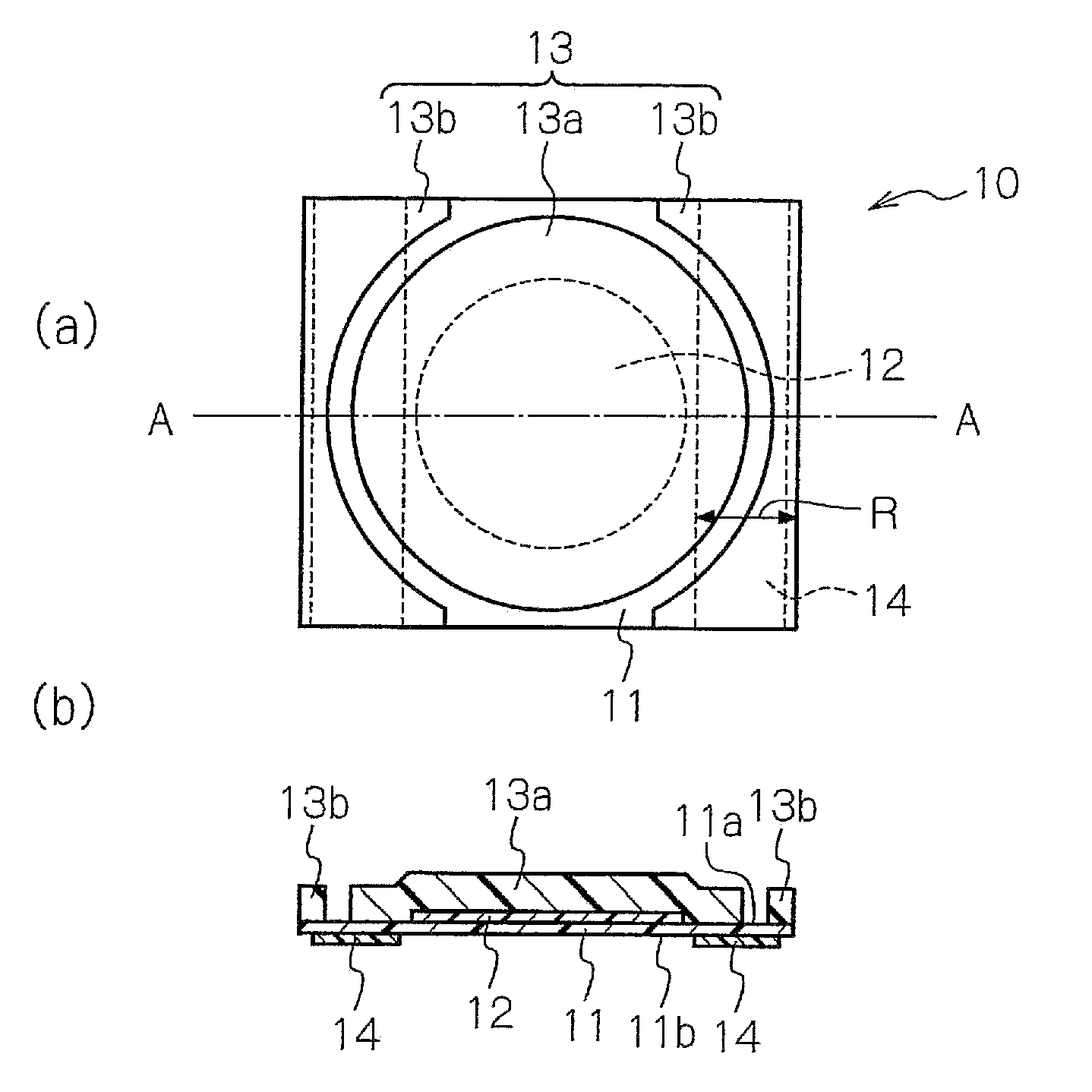
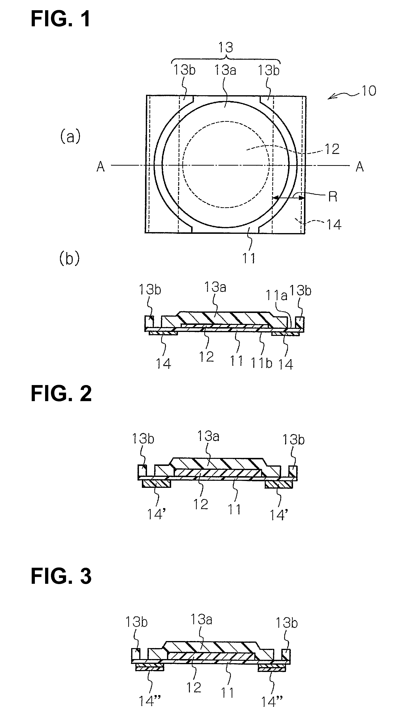
[0052]FIG. 1(a) is a plan view showing a wafer processing tape according to a first embodiment of the present invention, and FIG. 1(b) is a sectional view taken along the line A-A of FIG. 1(a).

[0053]As shown in FIGS. 1(a) and 1(b), a wafer processing tape 10 includes a release film 11 having a relatively long length, an adhesive layer 12, a pressure-sensitive adhesive film 13, and a support member 14.

[0054]The adhesive layer 12 is formed on a first surface 11a of the release film 11 and has a round label shape corresponding to the shape of the semiconductor wafer. The pressure-sensitive adhesive film 13 has a round label portion 13a adopted to cover the adhesive layer 12 in such a manner as to be brought into contact with the release film 11 around the adhesive layer 12 and a surrounding portion 13b adopted to su...

second embodiment

[0093]An explanation of a wafer processing tape according to a second embodiment of the present invention will be explained in detail with reference to the attached drawings.

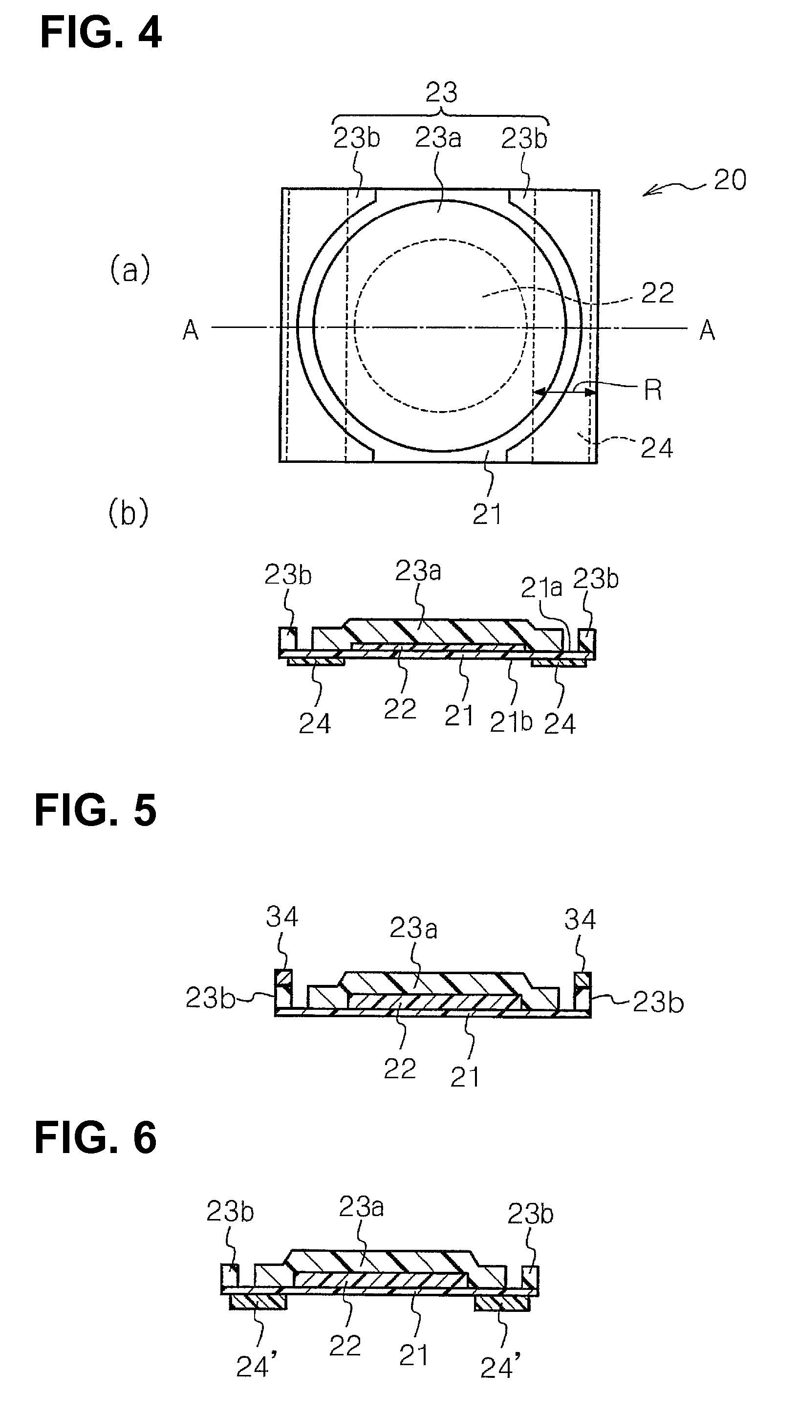
[0094]FIG. 4(a) is a plan view showing a wafer processing tape according to a second embodiment of the present invention, and FIG. 4(b) is a sectional view taken along the line A-A of FIG. 4(a).

[0095]As shown in FIGS. 4(a) and 4(b), a wafer processing tape 20 according to the present invention includes a release film 21 having a relatively long length, an adhesive layer 22, a pressure-sensitive adhesive film 23, and a colored support member 24.

[0096]The adhesive layer 22 is formed on a first surface 21a of the release film 21 and has a round label shape corresponding to the shape of the semiconductor wafer. The pressure-sensitive adhesive film 23 has a round label portion 23a adopted to cover the adhesive layer 22 in such a manner as to be brought into contact with the release film 21 around the adhesive layer 2...

example 1

[0159]The release film 2A on which the adhesive layer 3A is formed was moved from the refrigerator and was placed at a room temperature. Pre-cut processing for the adhesive layer 3A was carried out to a shape of a round having a diameter of 220 mm, while having a cut depth of 10 μm or less to the release film 2A. After that, the unnecessary portion on the adhesive layer 3A was removed, and so as to make the pressure-sensitive adhesive layer of the pressure-sensitive adhesive film 1A come into contact with the adhesive layer 3A, the release film 2A was laminated on the pressure-sensitive adhesive film 1A at a room temperature. Pre-cut processing for the pressure-sensitive adhesive film 1A was carried out to a shape of a round having a diameter of 290 mm in a concentric circle to the adhesive layer 3A, while having a cut depth of 10 μm or less to the release film 2A. Next, the support member 4A was attached at the both end portions of the release film 2A in a short side direction of t...


PUM

PropertyMeasurementUnit
temperatureaaaaaaaaaa
thicknessaaaaaaaaaa
thicknessaaaaaaaaaa

Abstract

A wafer processing tape includes a release film having a large length; an adhesive layer formed on a first surface of the release film and having a predetermined planar shape; a pressure-sensitive adhesive film having a label portion and a surrounding portion surrounding outside the label portion; and a support member formed on a second surface of the release film opposite to the first surface on which the adhesive layer and the pressure-sensitive adhesive film are formed. The label portion has a predetermined planar shape and covers the adhesive layer so that the label portion contacts with the release film around the adhesive layer. The support member is disposed at both end portions of the release film in a short side direction of the release film. The support member has a coefficient of linear expansion of 300 ppm / ° C. or less.

Description

CROSS-REFERENCE TO RELATED APPLICATIONS[0001]This is a divisional application of the prior application Ser. No. 12 / 675,593 filed Feb. 26, 2010, pending.TECHNICAL FIELD[0002]The present invention relates to a wafer processing tape. More particularly, the present invention relates to a wafer processing tape with functions of a dicing tape and a die bonding film.BACKGROUND ART[0003]Recently, a dicing die bonding tape has been developed, which has functions of a dicing tape adopted to fix a semiconductor wafer thereon in a dicing step where the semiconductor wafer is cut into individual chips, and a die bonding film (a die attach film) adopted to attach the semiconductor chip to a lead frame or a package substrate, or to stack the semiconductor chip in a stack package.[0004]The dicing die bonding tape is pre-cut in consideration of workability such as attachment to a semiconductor wafer, attachment to a ring frame in a dicing process, and the like.[0005]An example of the pre-cut dicing ...

Claims


Application Information

Patent Timeline
Patent Type & Authority Applications(United States)
IPC IPC(8): C09J7/02C09J7/20C09J7/40
CPCC09J7/02C09J2203/326H01L21/67132Y10T428/1467H01L2221/68327Y10T428/2878Y10T428/28H01L21/6836C09J7/20C09J7/40C09J7/403
Inventor MARUYAMA, HIROMITSUSAKUMA, NOBORUMORISHIMA, YASUMASAISHIWATA, SHINICHI
Owner FURUKAWA ELECTRIC CO LTD
Learn More