Electric connection box

An electrical connection box and connection terminal technology, applied in the field of electrical connection boxes, can solve the problems of complicated air flow paths of electronic components, and achieve the effect of preventing abnormally high temperature

Inactive Publication Date: 2012-07-18
AUTONETWORKS TECH LTD +2
View PDF1 Cites 0 Cited by
  • Summary
  • Abstract
  • Description
  • Claims
  • Application Information

AI Technical Summary

Problems solved by technology

[0006] However, the shape of the frame does not have to be cylindrical, and the air flow path of the electronic components on the circuit board housed in the frame becomes complicated.

Method used


Image

  • Electric connection box
  • Electric connection box
  • Electric connection box

Examples


Embodiment Construction

[0028] Embodiments of the present invention will be specifically described below with reference to the drawings.

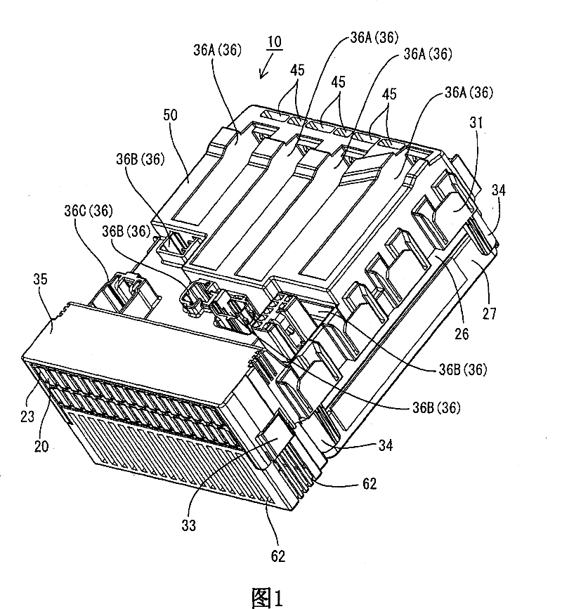
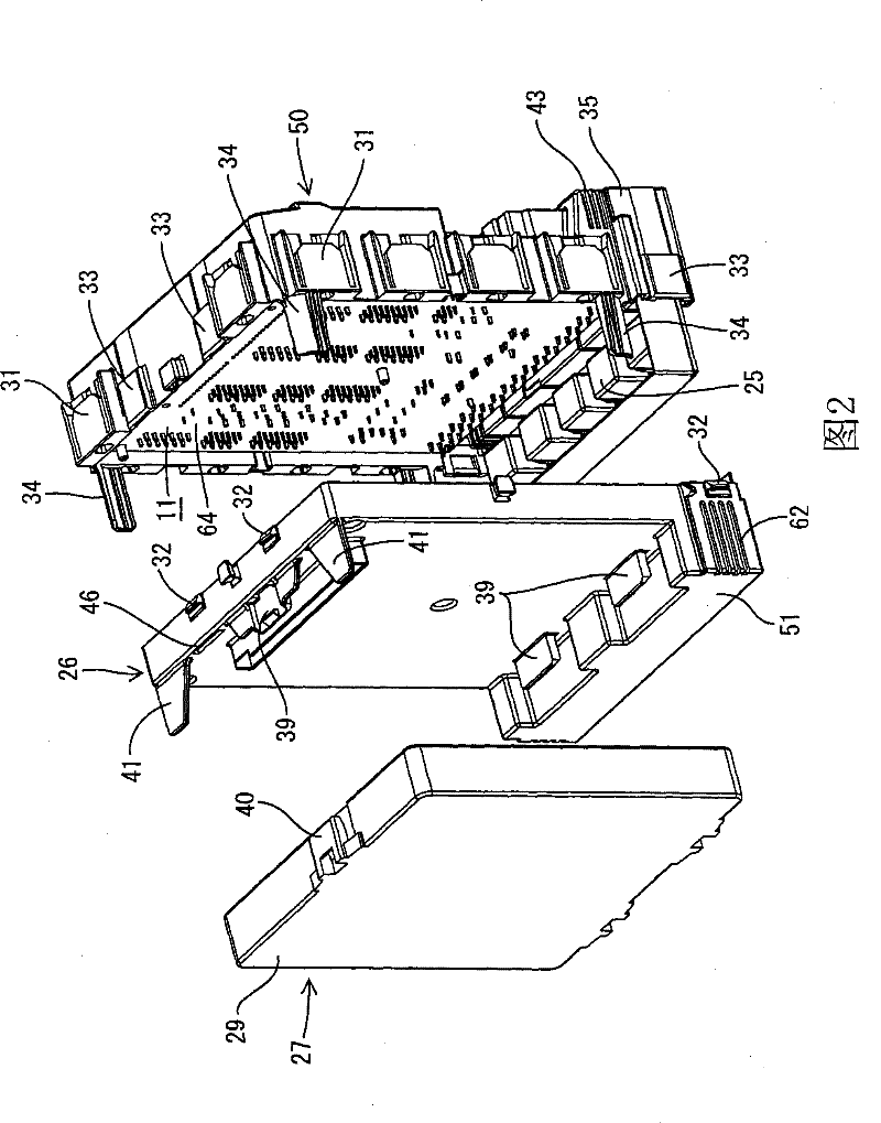
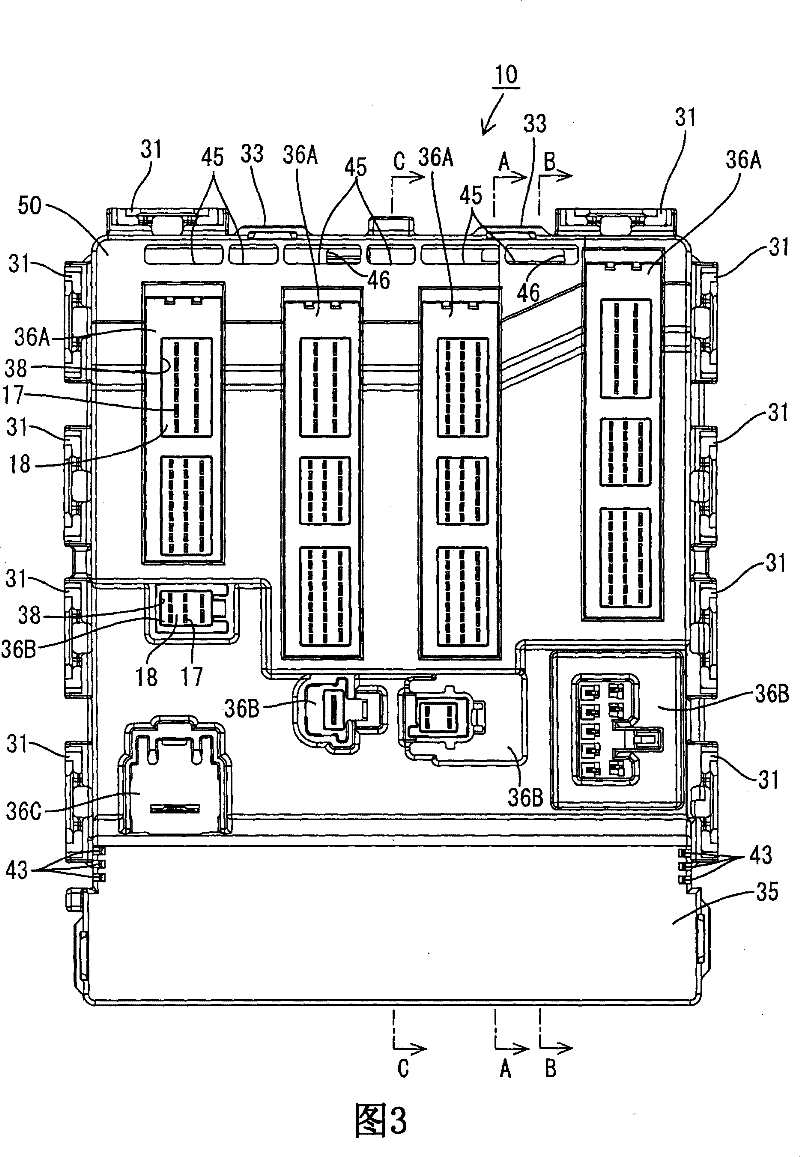
[0029] refer to Figure 1 to Figure 7 The first embodiment of the present invention will be described. The electrical connection box according to this embodiment is installed between a battery (not shown) and on-vehicle electrical components (not shown) such as lamps and power windows, and controls the power supply and shutdown of these on-vehicle electrical components. The electrical junction box is accommodated in a flat case 10 . The electrical connection box is as Image 6 The shown vertical orientation is installed in the interior of a car (not shown) and used. The vertical orientation means that the circuit board 11 is arranged in the casing 10 in a posture in which the board surface of the circuit board 11 is vertical.

[0030] (circuit board)

[0031] The circuit board 11 is substantially rectangular, and conductive paths (not shown) are formed on bot...


PUM


Abstract

An electric connection box according to the present invention can include a circuit board having a first surface capable of mounting an electronic component, and a second surface defining a non-mounting surface, a case vertically housing the circuit board, an air ventilation path extending between the non-mounting surface of the circuit board and an inner wall surface of the case by opposing the non-mounting surface of the circuit board to the inner wall surface in the case, a suction port positioned in the case and in communication with the ventilation path, an exhaust port positioned in thecase above said suction port and in communication with the ventilation path, and a heat generating component in communication with the ventilation path.

Description

technical field [0001] The present invention relates to an electrical connection box formed by accommodating a circuit board in a casing. Background technique [0002] Conventionally, an electrical junction box described in Patent Document 1 (Japanese Patent Application Laid-Open No. 2006-19711 ) is known as an electrical junction box. In this electrical connection box, a substrate on which a heat generating component is mounted is housed in a frame. A metal heat collecting portion is fixed to the substrate, and a cylindrical portion exposed to the outside of the housing is fixed to the heat collecting portion. A heat dissipation window is formed on an upper portion of the cylindrical portion, and an intake window is formed on a lower portion. [0003] In the above-mentioned electrical connection box, the heat generated from the heat-generating component is conducted from the substrate through the heat collecting part to the cylindrical part exposed outside the frame, and ...

Claims


Application Information

Patent Timeline
Patent Type & Authority Patents(China)
IPC IPC(8): H02G3/16H02G3/08H05K7/20
Inventor 桥仓学清水达哉西田太
Owner AUTONETWORKS TECH LTD
Why Eureka
Try Eureka