Tire vulcanizing apparatus

A tire vulcanization and tire technology, which is applied to tires, other household appliances, household appliances, etc., can solve the problems of time and labor, and the inability to ensure the accuracy of the abutting part, so as to prevent partial wear, shorten processing time, manufacture and install easy effect

Active Publication Date: 2008-05-28
MITSUBISHI HEAVY IND MACHINERY SYST LTD
View PDF2 Cites 13 Cited by
  • Summary
  • Abstract
  • Description
  • Claims
  • Application Information

AI Technical Summary

Problems solved by technology

For this reason, there is a problem that time and labor are required for the division and machining of the upper and lower discs
In addition, there is a problem that accuracy cannot be ensured due to abrasion of the contact portion, etc.

Method used


Image

  • Tire vulcanizing apparatus
  • Tire vulcanizing apparatus
  • Tire vulcanizing apparatus

Examples


Embodiment Construction

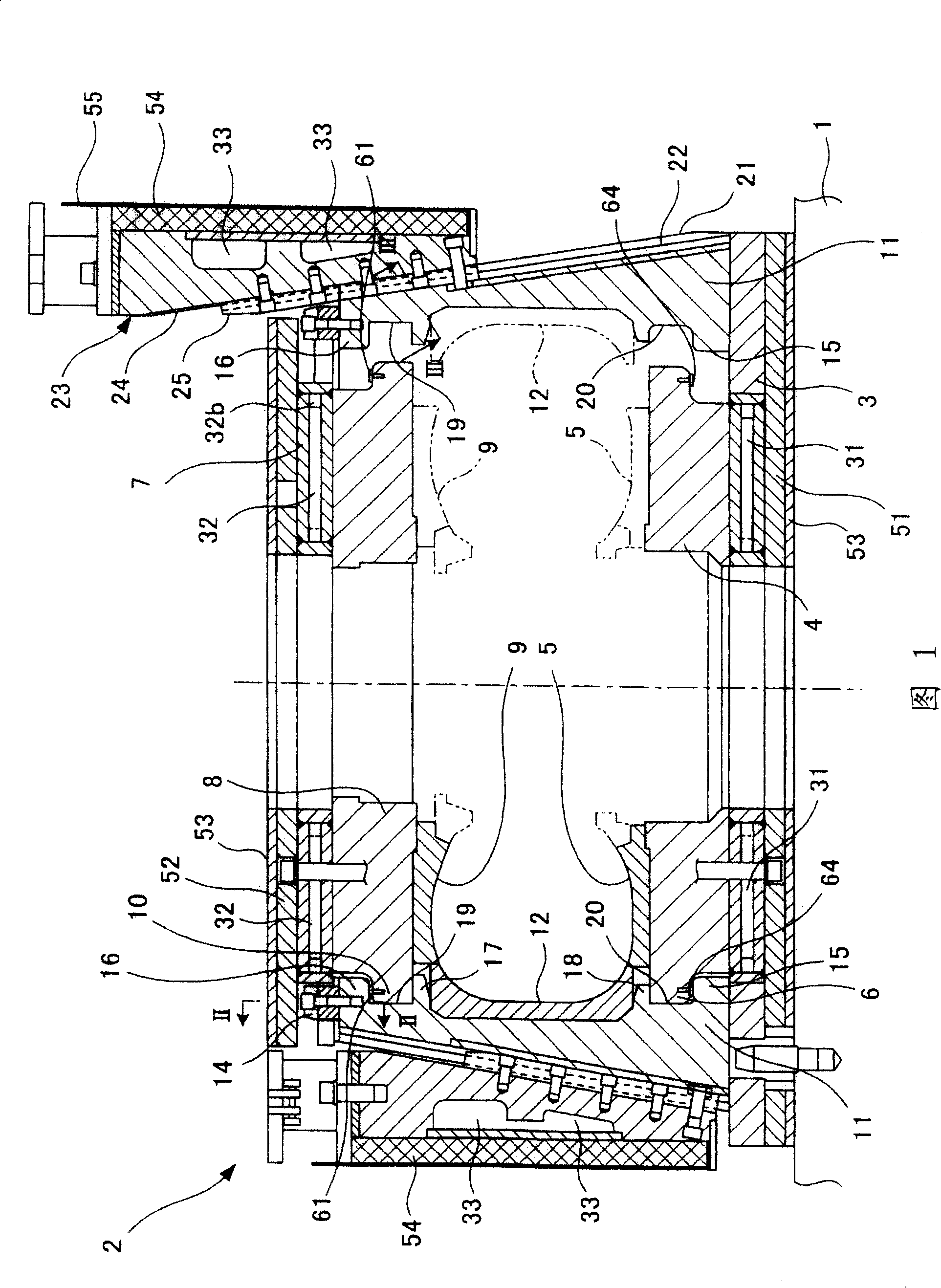
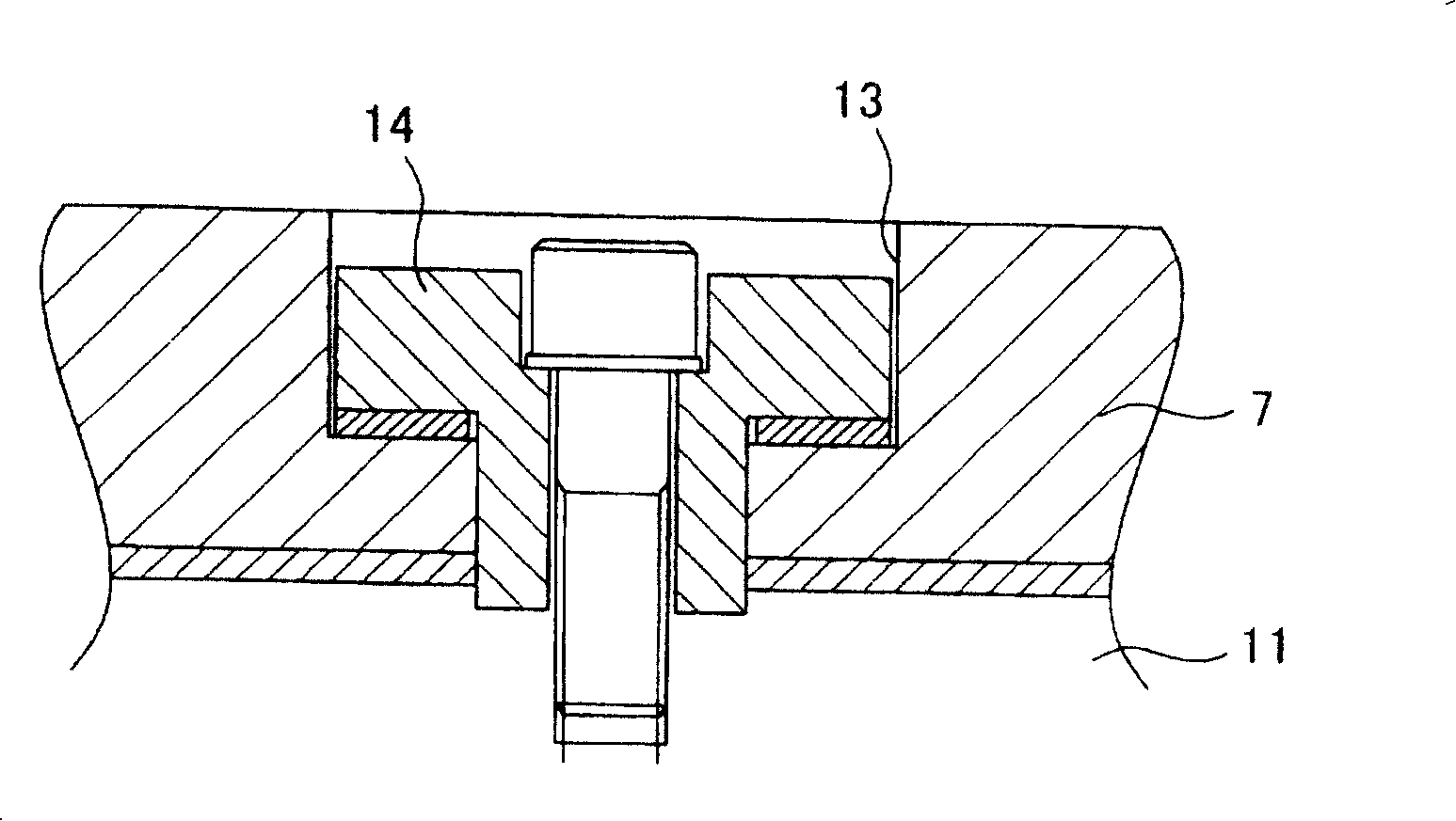
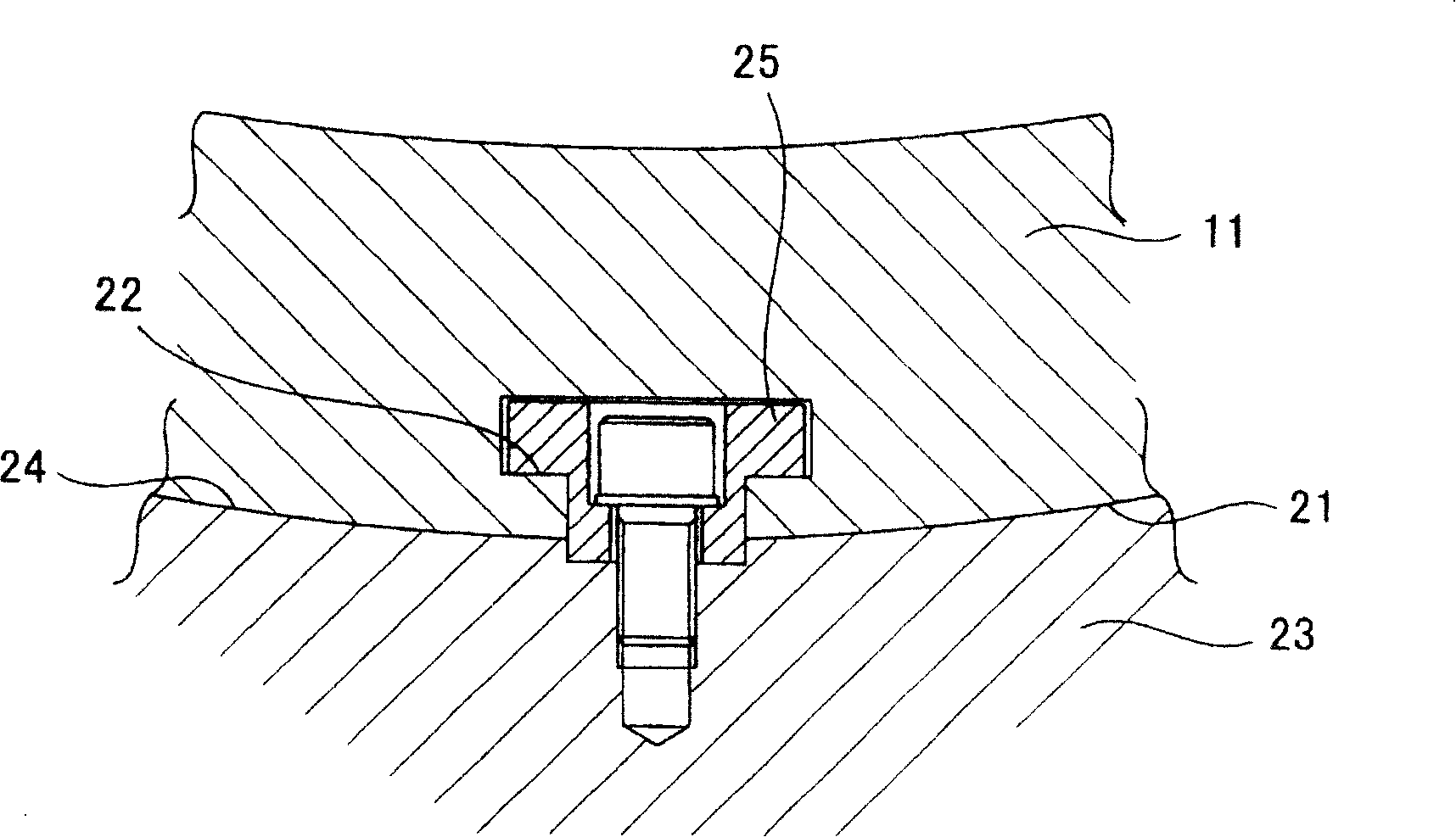
[0049] Next, the tire vulcanizer of the present invention will be described in detail based on examples. Fig. 1 is a partial sectional view of the tire vulcanizing device of the embodiment, the left side of the center line shows the state of locking the tread mold, and the right side of the center line shows the state of reaching the tread mold, figure 2 , image 3 It is the II-II arrow sectional view and III-III arrow sectional view in Fig. 1, Figure 4 is the plan view of the upper plate. Figure 5 , Figure 6 is a sectional view of the upper adjustment plate installed state, Figure 7 , Figure 8 It is a cross-sectional view of the installation state of the lower adjustment plate.

[0050] The main body of the tire vulcanizer includes a fixed base 1 on which a mold container 2 is formed. On the base 1 is fixed a lower pressure plate 3 which is an annular disc serving as a base of the mold container 2 . On the lower pressing plate 3 , an annular lower circular plate (...


PUM


Abstract

Disclosed is a tire vulcanizing apparatus including upper and lower circular plates (4,8), to which sidewall dies (5,9) for forming side portions of a tire are attached; respectively; and plural segments (11), to which tread dies (12) separated as plural pieces for forming a tread portion of the tire are attached; respectively, in which apparatus, the upper and lower circular plates (4,8) are held by engagement of lug portions(15,16), formed respectively on upper and lower portions of the segments (11), with protrusions (6,10) on outer circumferential portions of the upper and lower circular plates (4,8) so as to prevent the upper and lower circular plates (4,8) from moving away from each other, the apparatus being constituted by providing adjustment plates (61,64) used for maintaining a measurement between the upper and lower circular plates (4,8), to an interface between the protrusion (6,10) of each of the upper and lower circular plates 84,8) and a corresponding one of the lug portions (15,16)of each segment (11).

Description

technical field [0001] The invention relates to a tire vulcanizing device for forming and vulcanizing raw rubber tires. Background technique [0002] In tire manufacturing, a tire vulcanizer using a lock container is known as an apparatus for molding and vulcanizing a raw rubber tire. Such a tire vulcanizer is disclosed in, for example, Japanese Patent No. 2505675 (Patent Document 1), Japanese Unexamined Patent Publication No. 2001-79850 (Patent Document 2), and the like. [0003] As described in these gazettes, in a vulcanization apparatus using a self-locking container, the self-locking container as a part for forming a tire forms a metal mold container (metal mold device) basically composed of a part that holds the molded tire. The upper sidewall mold (metal mold) of the sidewall part and the upper circular plate (upper plate) and lower circular plate (lower plate) of the lower sidewall mold (metal mold); the tread mold ( metal mold) divided into multiple blocks; and an...

Claims


Application Information

Patent Timeline
Patent Type & Authority Applications(China)
IPC IPC(8): B29C35/02B29C33/20B29C33/30B29C33/34B29L30/00
CPCB29C33/303B29D30/0629B29D2030/063B29C35/02
Inventor 日根野义克村上俊文
Owner MITSUBISHI HEAVY IND MACHINERY SYST LTD
Why Eureka
Try Eureka