
Photographic camera automatic rocking-pickup device

A camera, automatic technology, applied to the camera body, camera, support machine, etc.

Inactive Publication Date: 2008-06-04
LEJIN ELECTRONICS KUNSHAN COMPUTER CO LTD
View PDF0 Cites 0 Cited by
  • Summary
  • Abstract
  • Description
  • Claims
  • Application Information

AI Technical Summary

Problems solved by technology

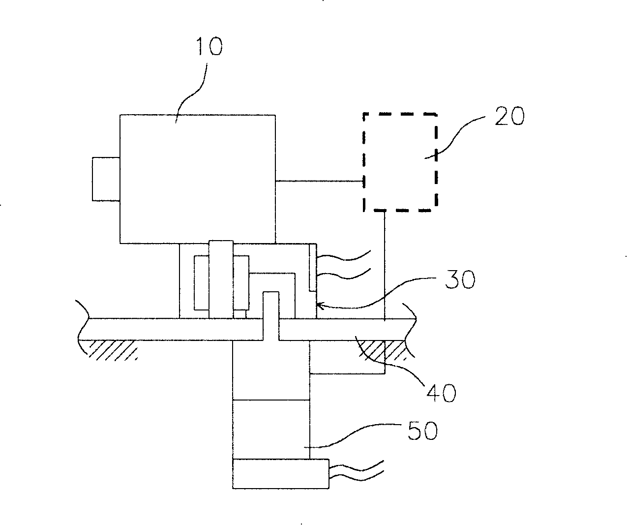
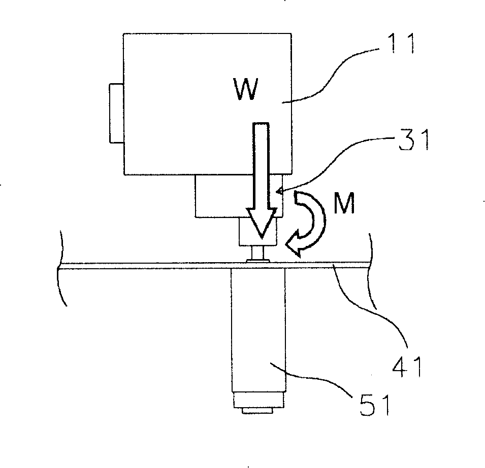
But if you want to reduce the loss of precision in the process of power transmission, such as figure 2 As shown, when all the mass is directly applied to the output shaft, due to the direct transmission of the load, the durability, reliability, material, strength, and production cost of the output shaft of the spindle motor or the spindle motor with the reducer will be greatly affected. question

Method used


Image

  • Photographic camera automatic rocking-pickup device
  • Photographic camera automatic rocking-pickup device
  • Photographic camera automatic rocking-pickup device

Examples


Embodiment Construction

[0037] Hereinafter, the present invention will be described in detail through examples and drawings.

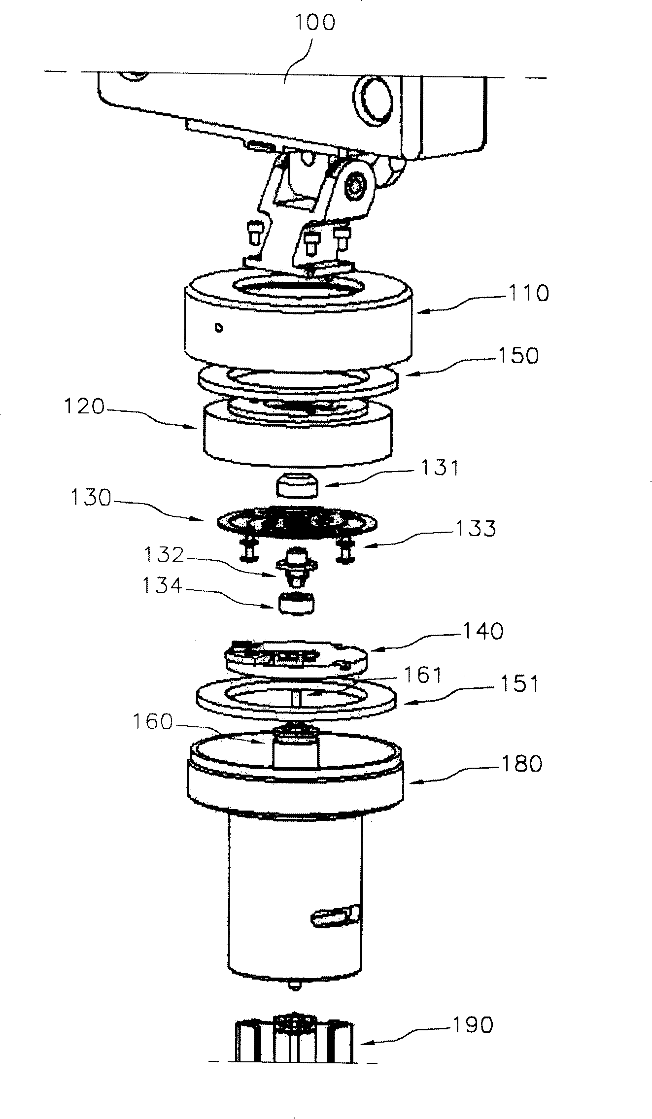
[0038] image 3 It is an exploded perspective view showing each component of the present invention. The present invention is characterized in that the load on the camera unit is distributed, and most of the load is transmitted to structures other than the spindle motor, such as the cover, to greatly reduce the load on the output shaft of the spindle motor.

[0039] The present invention is based on the fixed part 190 and enables the camera part 100 to perform a horizontal rotation movement of the panning device. It consists of the following parts: the cover and cover that form the shape; the main shaft motor that generates power; the rotor installed in the above-mentioned camera; the coupler that connects the main shaft motor and the rotor; Bearings for cover transmission.

[0040] A space for accommodating the spindle motor 160 is formed inside the covering cover 180 , an...


PUM


Abstract

The present invention relates to an automatic panning device, which prevents the load in the direction of a rotating shaft from being directly transmitted to an output shaft of a motor or a speed reducer, and simultaneously uses a coupling device maximatily maintaining the precision of the output shaft to ensure the smooth execution of the horizontal rotation of a camera executing panning actions. The present invention is formed by the following parts of a covering hood, a coupler, a rotor, a cover plate and a bearing, wherein, the covering hood is integrated with a fixed part and arranged for leading an output shaft of a main shaft motor inside the cover hood to be vertical; the central part of the coupler is fixed and rotates integrally with the output shaft of the main shaft motor; the coupler is provided with a leaf spring capable of rotating in the horizontal direction; the rotor is connected with the leaf spring and arranged for fixing a camera part capable of inputting external images; the cover plate protects the coupler and the rotor from the external, is connected with the covering hood, and has the upper part provided with a connecting hole capable of connecting the rotor mutually with the camera part; the bearing is in contact support with the upper part and lower part of the rotor.

Description

technical field [0001] The present invention relates to a camera panning device and its structure, in particular to preventing the load in the direction of the rotating shaft from being directly transmitted to the output shaft of the motor or reducer, and at the same time using a coupling device that maintains the precision of the output shaft to the maximum extent to enable the panning action Automatic panning mechanism for smooth horizontal camera rotation. Background technique [0002] A panning device is a device that installs a specific image input device such as a camera, rotates the image input device at an ideal speed and angle, and moves the camera to shoot according to the speed or direction of the moving object. It can be used for various purposes such as robot vision, security surveillance, and monitoring. [0003] The panning device of a general camera has a structure that manually or automatically horizontally rotates and moves a mass load composed of a camera...

Claims


Application Information

Patent Timeline
IPC IPC(8): G03B17/56H04N5/225H04N5/232F16M11/00
Inventor 张在元
Owner LEJIN ELECTRONICS KUNSHAN COMPUTER CO LTD
Learn More