Supercharge Your Innovation With Domain-Expert AI Agents!

Top roll support and loading arm

A technology of loading arm and load level, applied in the direction of textile and paper making, drafting equipment, spinning machine, etc., can solve the problem of not being able to check quickly

Active Publication Date: 2008-06-04
SAURER COMPONENTS GMBH
View PDF2 Cites 4 Cited by
  • Summary
  • Abstract
  • Description
  • Claims
  • Application Information

AI Technical Summary

Problems solved by technology

[0008] Therefore, in the prior known top roller supports and loading arms it is not always possible to quickly check at the same time whether the respective required loads of the different top rollers of the top roller supports and loading arms are correctly adjusted

Method used


Image

  • Top roll support and loading arm
  • Top roll support and loading arm
  • Top roll support and loading arm

Examples


Embodiment Construction

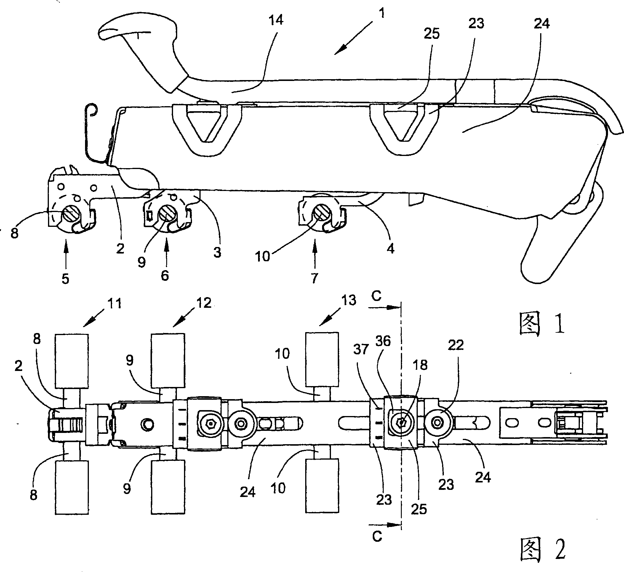
[0041] Figure 1 shows the longitudinal side of a top roller support and loading arm 1 of a drafting device of a spinning machine in an operative position with adjustable clamping means for the top rollers. The relevant top view in FIG. 2 shows the top roller support and loading arm 1 without the operating lever 14, so that the support profile 24 of the top roller supporting and loading arm 1 is shown in such a way that when the operating lever 14 is folded upwards, the support profile Item 24 appears in the operator's field of view. The gripping device comprises grippers 2 , 3 , 4 for respective top rollers, each arranged as output roller 11 , center roller 12 and input roller 13 . The top rollers are configured as double rollers and are rotatably clamped with their axes 8 , 9 , 10 in receptacles 5 , 6 , 7 of the grippers 2 , 3 , 4 .

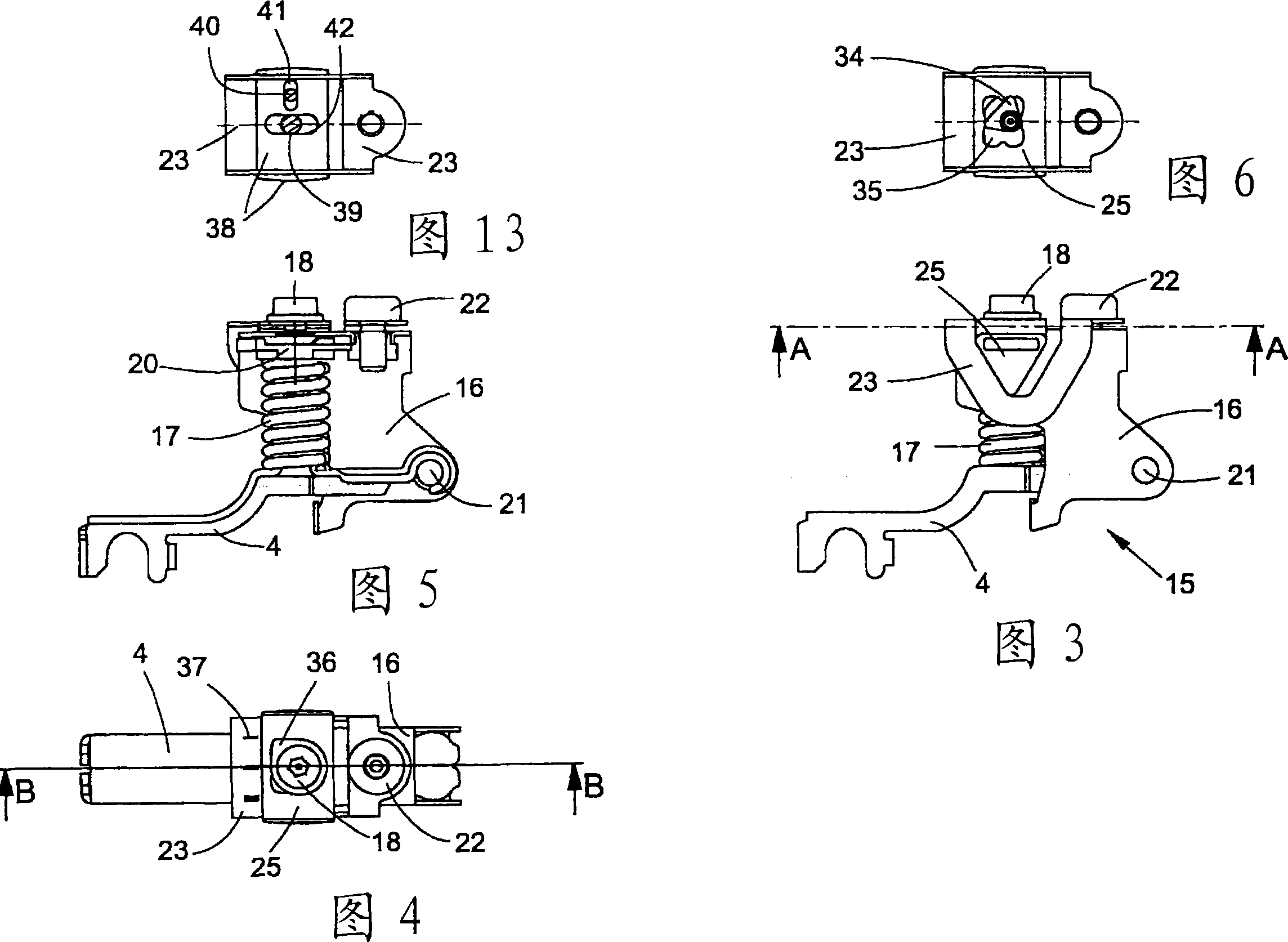
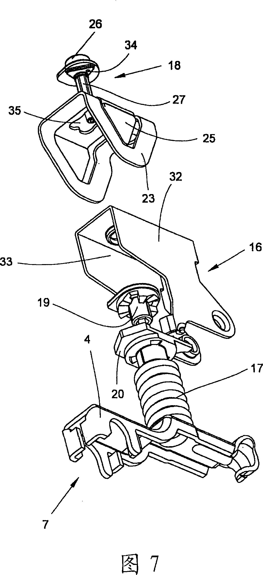
[0042] For better clarity, Figures 3, 4, 5, 6 and 7 respectively represent a clamping device 15 without a support profile 24, which clamping d...


PUM


Abstract

The top roll support and loading arm (1) for a spinning machine drawing frame comprises holding devices for holding the top rolls. At least one of the holding devices is assigned a spring element for loading the associated top roll. The loading takes place by means of a loading element which acts on the spring element and can be set by an adjusting element. The adjusting element is at least largely covered in the operating position of the drawing frame. There is an adjustable display means (25) for displaying the magnitude of the loading. The display means (25) can move relative to the top roll support and loading arm (1) and is coupled to the adjusting element in such a way that its position changes with the setting position of the adjusting element. The display means (25) is arranged such that it can be seen readily at any time, irrespectively of the position of the top roll support and loading arm (1).

Description

technical field [0001] The invention relates to a top roller support and loading arm according to the preamble of claim 1 . Background technique [0002] Spinning machine drafting devices usually have a top roller bearing and a loading arm, wherein the top roller can be loaded separately by means of spring elements. In order to obtain ideal operating conditions, the load pressure acting on the individual top rollers can be adjusted as finely as possible and thus adapted to the respective spinning conditions. [0003] Top roller supports and loading arms of this type are known, eg from DE-AS-1087496. The top roller is fixed on a guide arm which, together with its loading spring and the substantially U-shaped or bow-shaped slide, forms a movable and fixable unit within the top roller support and loading arm. This type of unit can be completely removed as a module from the top roller support and loading arm, and the spring load can be adjusted in the removed state. The indiv...

Claims


Application Information

Patent Timeline
Patent Type & Authority Applications(China)
IPC IPC(8): D01H5/50
CPCD01H5/505D01H5/46D01H5/50
Inventor 约阿希姆·迪德里希
Owner SAURER COMPONENTS GMBH
Features
  • R&D
  • Intellectual Property
  • Life Sciences
  • Materials
  • Tech Scout
  • Unparalleled Data Quality
  • Higher Quality Content
  • 60% Fewer Hallucinations
Learn More