
Laminated slab

A technology of laminating slabs and bottom plates, applied in the direction of floors, building components, buildings, etc., can solve the problems of affecting the two-way force balance of floor slabs, difficult construction period and high cost, and achieve the effect of ensuring application safety.

Inactive Publication Date: 2008-06-18
邱则有
View PDF0 Cites 3 Cited by
  • Summary
  • Abstract
  • Description
  • Claims
  • Application Information

AI Technical Summary

Problems solved by technology

[0002] At present, the reinforced concrete floor slabs used in China include cast-in-place floor slabs and prefabricated floor slabs. The difficulty is high, the loss of the formwork is large, and the cost is high. The prefabricated floor does not require on-site formwork, the construction period is short, and the cost is low. However, the prefabricated components are heavy and difficult to hoist. Cracks are prone to occur at the splicing parts of the components, and the integrity is poor. For example, the patent number is ZL0322765. 2. The patent titled a reinforced concrete assembled floor slab discloses a reinforced concrete prefabricated component. The prefabricated component is composed of plates and ribs, and the ribs have holes for piercing steel bars. The effective height of the steel bars in the pouring concrete is greatly reduced, which affects the two-way force balance of the floor slab, and it is difficult to form an equivalent two-way slab, etc.

Method used


Image

  • Laminated slab
  • Laminated slab
  • Laminated slab

Examples


Embodiment Construction

[0054] The present invention will be further described below in conjunction with the accompanying drawings and embodiments.

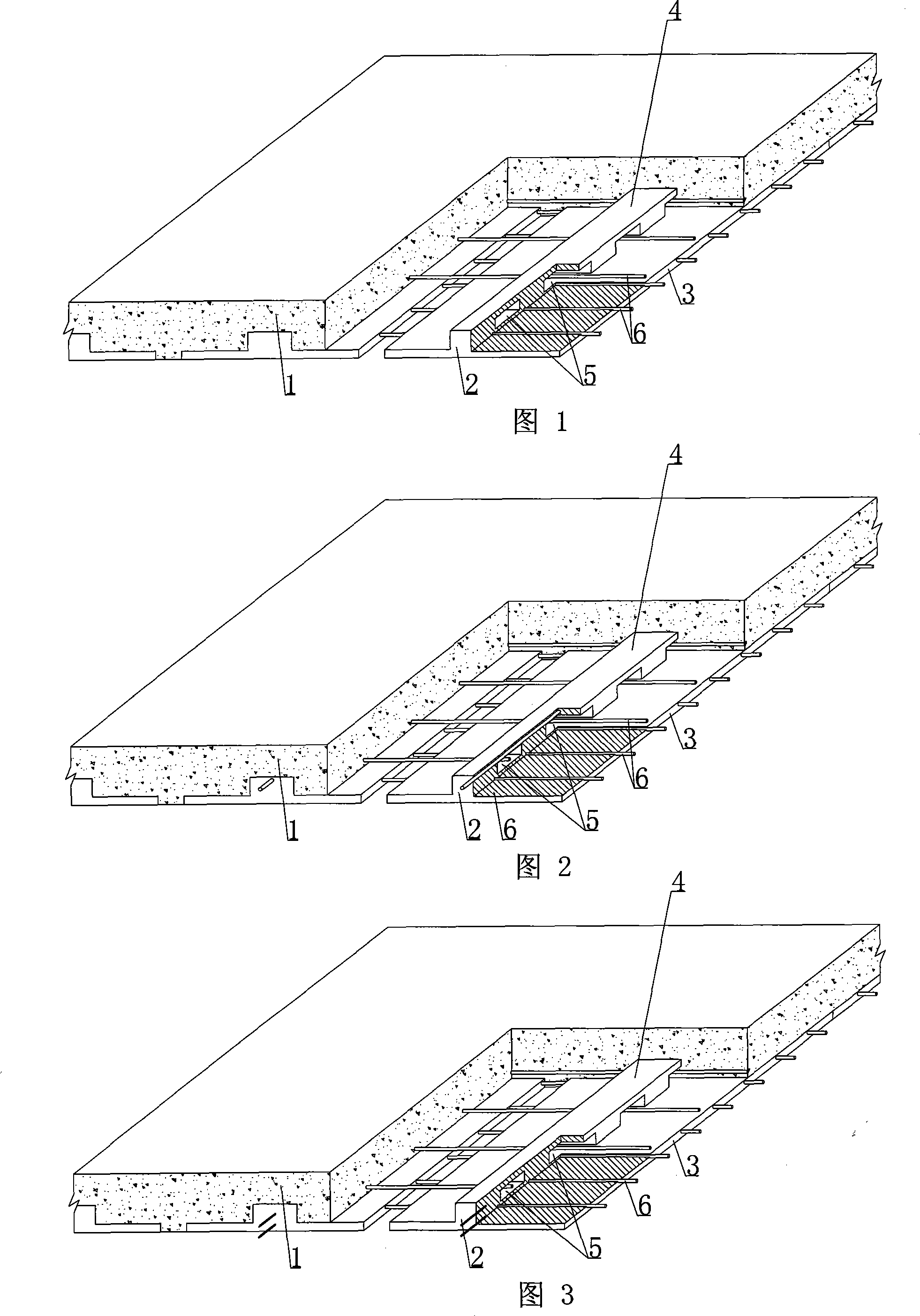
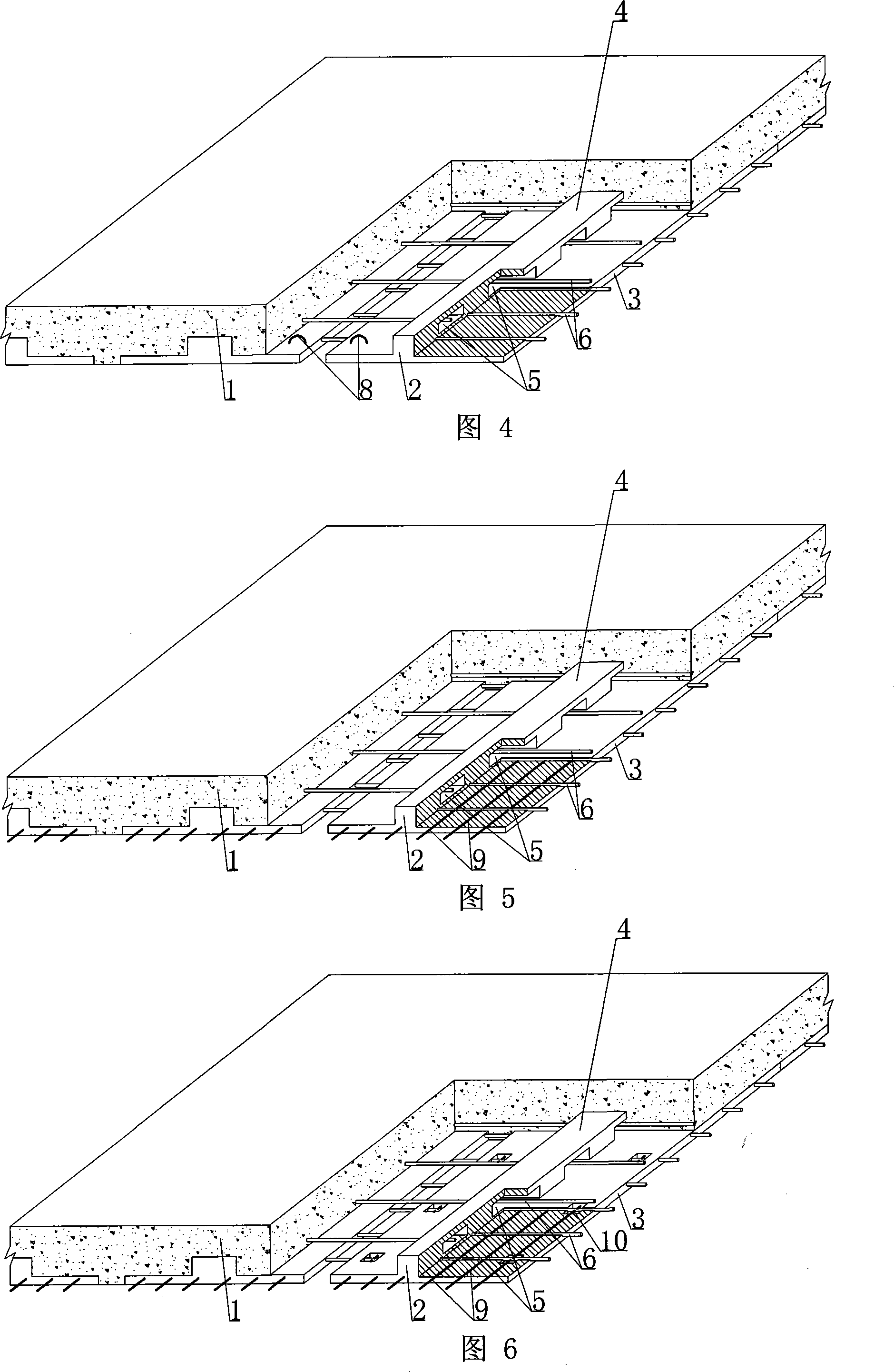
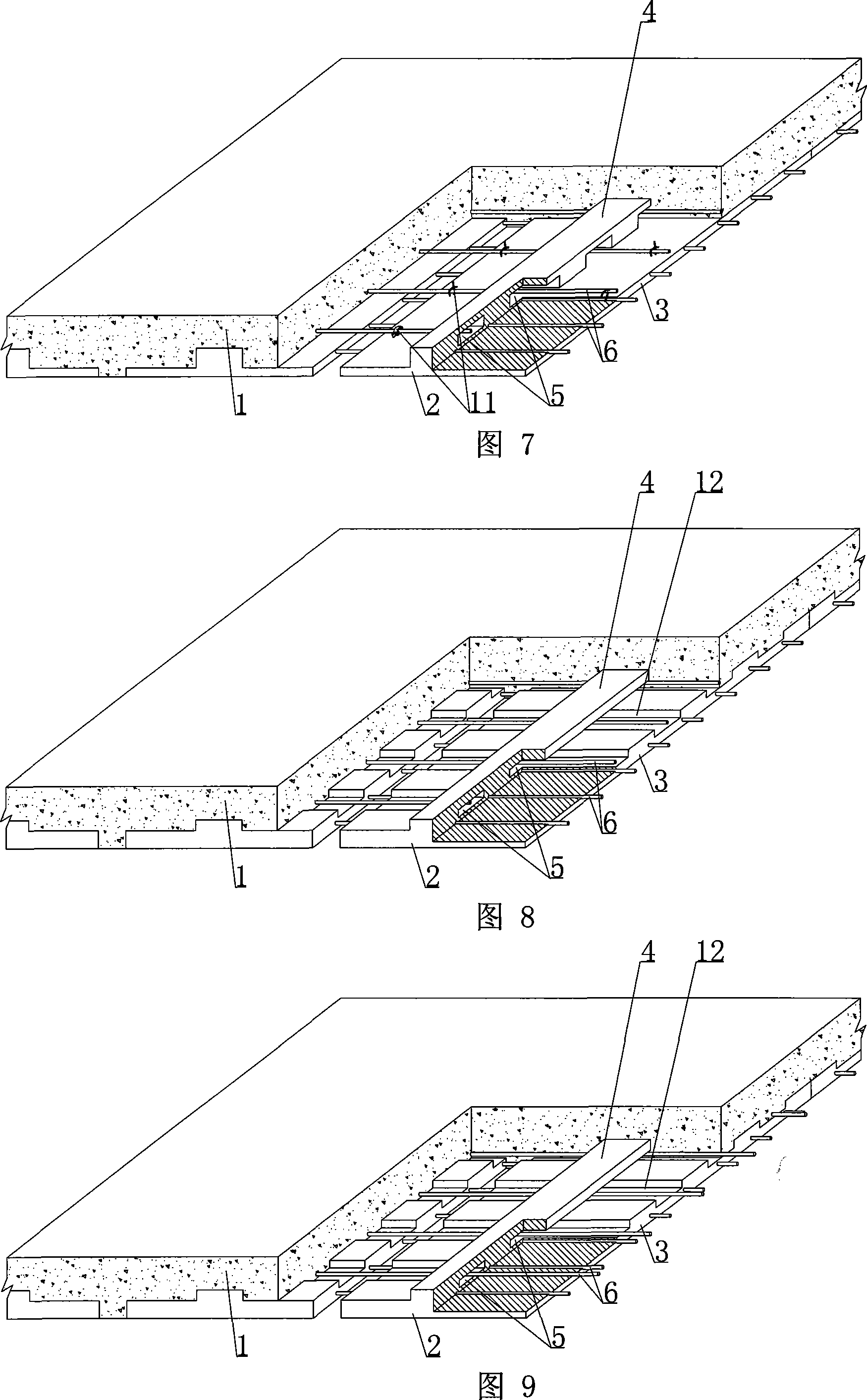
[0055] As shown in the accompanying drawings, the present invention includes reinforced concrete 1 and reinforced concrete ribbed prefabricated slab 2, the reinforced concrete ribbed prefabricated slab 2 is arranged at the bottom of the laminated slab, and the reinforced concrete ribbed prefabricated slab 2 includes a reinforced concrete strip bottom plate 3 , the reinforced concrete longitudinal long rib 4 is characterized in that there is a hole 5 transversely penetrating the long rib 4 or\ and the bottom plate 3, and there is at least one transverse prestressed steel bar 6 or one or both ends of the horizontal prestressed steel bar 6 in the long bottom plate 3 At the same time, it is exposed and anchored in the reinforced concrete 1, and the transverse prestressed steel bar 6 is pierced through the hole 5 on the longitudinal long rib 4. After pouring ...


PUM

PropertyMeasurementUnit
Lengthaaaaaaaaaa
Lengthaaaaaaaaaa
Widthaaaaaaaaaa

Abstract

A laminate comprises a reinforced concrete (1) and a reinforced concrete precast ribbed slab (2), wherein, the reinforced concrete ribbed precast slab (2) is arranged on the bottom of the laminate and comprises a long reinforced concrete bottom board (3) and a longitudinal long reinforced concrete rib (4), holes (5) transversely penetrate the long rib (4) or / and the bottom board (3), at least one transverse prestressed reinforcing steel bar (6) is arranged in the the long bottom board (3), one end or both ends of the transverse prestressed reinforcing steel bar (6) are exposed and anchored in the reinforced concrete (1), and the transverse prestressed reinforcing steel bar (6) penetrates the hole (5) of the longitudinal long rib (4) and, after concrete is poured, forms a cast-in-situ, precast load-bearing laminate with bidirectional structures. Consequently, the present invention is applicable to superposed floors, floors, walls, foundation slabs and bridges, which apply cast-in-situ reinforced concrete or prestressed reinforced concrete, and the present invention is particularly applied to superposed floors.

Description

(1) Technical field [0001] The invention relates to a laminated board. (2) Background technology [0002] At present, the reinforced concrete floor slabs used in China include cast-in-place floor slabs and prefabricated floor slabs. The cast-in-place floor slabs have good integrity, but they need to be molded on site, and then concrete is poured. The construction period is difficult, the loss of the formwork is large, and the cost is high. formwork, short construction period and low cost, but the prefabricated components are self-heavy, difficult to hoist, cracks are prone to occur at the splicing parts of the components, and the integrity is poor, such as the patent No. ZL0322765. A reinforced concrete prefabricated component. The prefabricated component is composed of slabs and ribs, and the ribs have holes for passing steel bars. The thickness of the slab is large, which greatly reduces the effective height of the steel bars placed in the cast-in-place concrete, which aff...

Claims


Application Information

Patent Timeline
IPC IPC(8): E04B5/02E04B5/17
Inventor 邱则有
Owner 邱则有
Learn More