Resource monitoring method and device

A resource monitoring and resource technology, which is applied in the field of resource monitoring between network management interfaces, can solve problems such as lack of resource occupancy, and achieve the effect of improving centralization and improving management efficiency

Active Publication Date: 2011-12-07
ELECTRIC POWER SCI RES INST OF STATE GRID XINJIANG ELECTRIC POWER
View PDF0 Cites 0 Cited by
  • Summary
  • Abstract
  • Description
  • Claims
  • Application Information

AI Technical Summary

Problems solved by technology

[0006] The present invention is to solve the technical problem that the existing network management interface technology lacks the means for monitoring the operation and resource occupation of the EMS system by the NMS. The main purpose of the present invention is to provide a resource monitoring method and device for network The management system monitors the network element management system

Method used


Image

  • Resource monitoring method and device
  • Resource monitoring method and device
  • Resource monitoring method and device

Examples


no. 1 example

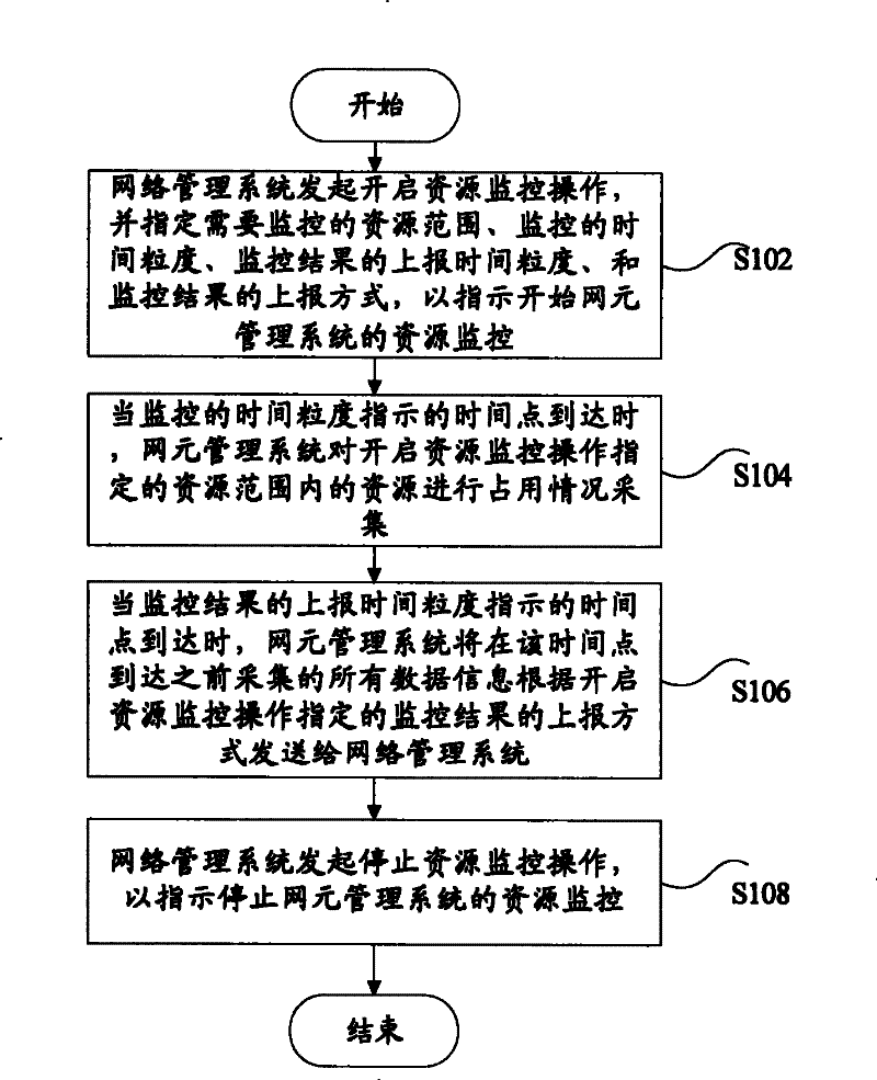
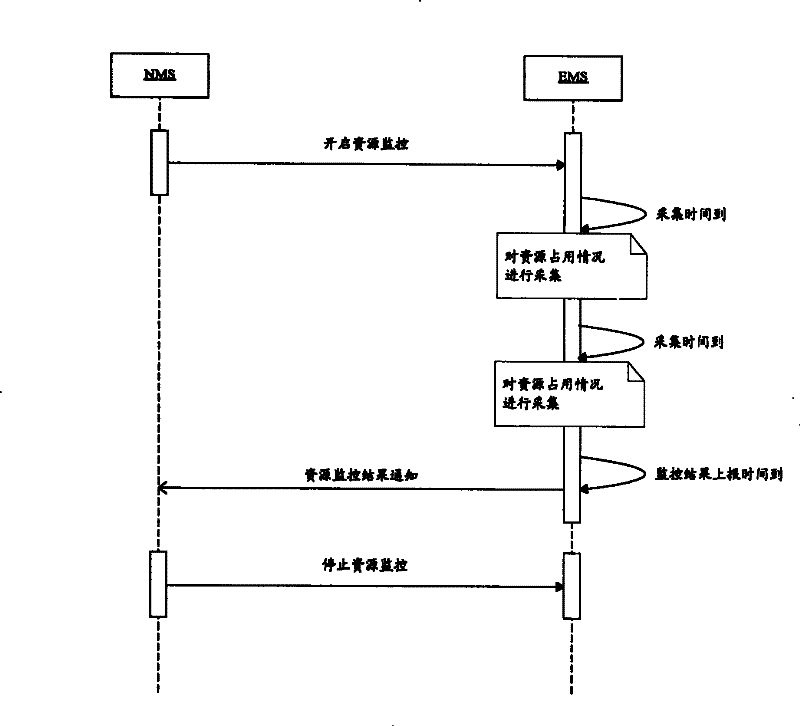
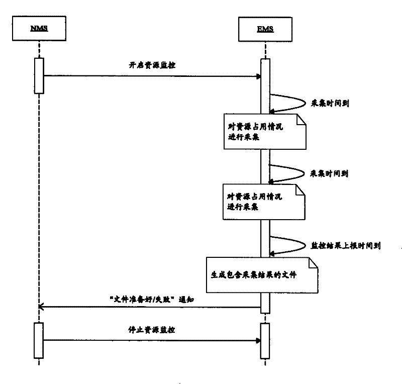
[0021] first refer to figure 1 , figure 2 with image 3 A first embodiment of the present invention is described. figure 1 is a flow chart of the resource monitoring method according to the first embodiment of the present invention, figure 2 It is a signaling flow chart using notification reporting in the resource monitoring method according to the first embodiment of the present invention, image 3 It is a signaling flow chart using file reporting in the resource monitoring method according to the first embodiment of the present invention.

[0022] Such as figure 1 As shown, the resource monitoring method according to the first embodiment of the present invention includes the following steps: Step S102, the network management system initiates the resource monitoring operation, and specifies the resource range to be monitored, the time granularity of monitoring, the reporting time granularity of monitoring results, and the reporting method of the monitoring result, to i...

no. 2 example

[0032] The following will refer to Figure 4 A second embodiment of the present invention is described. Figure 4 is a block diagram of a resource monitoring device 400 according to the second embodiment of the present invention.

[0033] Such as Figure 4 As shown, the device includes: a start resource monitoring operation initiation module 402, located on the network management system side, for initiating a start resource monitoring operation, and specifying the scope of resources to be monitored, the time granularity of monitoring, the time granularity of reporting monitoring results, and The reporting method of monitoring results; the occupancy collection module 404 is located on the side of the network element management system, and is used to collect the occupancy of resources within the resource range specified by the resource monitoring operation when the time point indicated by the monitoring time granularity arrives; The monitoring result reporting module 406 is lo...


PUM


Abstract

The invention discloses a resource monitoring method, which includes the following steps: first, a network management system initiates a resource monitoring operation, and specifies the scope of resources to be monitored, the time granularity of monitoring, the time granularity of reporting monitoring results, and The method of reporting the monitoring results is to instruct the resource monitoring of the network element management system to start; in the second step, when the time point indicated by the monitoring time granularity arrives, the network element management system will start resource monitoring within the resource range specified by the resource monitoring operation. Occupancy status collection; the third step, when the time point indicated by the reporting time granularity of the monitoring results arrives, the network element management system will report all the data information collected before the time point according to the monitoring result reporting method specified by enabling the resource monitoring operation and send it to the network management system; and the fourth step, the network management system initiates an operation of stopping resource monitoring to instruct to stop the resource monitoring of the network element management system.

Description

technical field [0001] The present invention relates to the communication field, and in particular, relates to a resource monitoring method and device between network management interfaces. Background technique [0002] The interface between the network management system (NMS) and the network element management system (EMS) is called Itf-N interface. EMS mainly completes the network element management layer (EML) function in ITU TMN, that is, completes the management function of one or more mobile communication devices. Usually, EMS between different equipment suppliers cannot be used universally. NMS mainly completes the network management layer (NML) function in ITU TMN, and is responsible for the management of all network elements in a managed network. For the situation that there are multiple equipment suppliers in the managed network (called a subnet), the purpose of managing the entire subnet can be achieved through EMS management. [0003] In the Itf-N interface, so...

Claims


Application Information

Patent Timeline
Patent Type & Authority Patents(China)
IPC IPC(8): H04L12/24
Inventor 熊康建沈毅黄树强
Owner ELECTRIC POWER SCI RES INST OF STATE GRID XINJIANG ELECTRIC POWER
Why Eureka
Try Eureka