Supercharge Your Innovation With Domain-Expert AI Agents!

Brake power generator for a hydraulic vehicle braking system

A vehicle braking and braking force technology, which is applied to electric braking systems, brakes, vehicle components, etc., can solve the problems of complex structure, complex assembly and design, and large structural volume of the braking system, so as to avoid large structural volume Effect

Inactive Publication Date: 2008-06-25
LUCAS AUTOMOTIVE GMBH
View PDF8 Cites 19 Cited by
  • Summary
  • Abstract
  • Description
  • Claims
  • Application Information

AI Technical Summary

Problems solved by technology

[0006] The above solutions in the prior art actually have the advantage of partial or even complete separation of brake force generation from brake pedal actuation, but they require very complex assembly and design
In particular, the above-mentioned brake systems equipped with electronic actuators according to the prior art are complex in structure and therefore expensive to produce
Another disadvantage of the system described above is that the pedal reaction force simulation device used therein is in any case arranged directly on the force input element engaging the brake pedal, which results in a relatively large construction volume

Method used


Image

  • Brake power generator for a hydraulic vehicle braking system
  • Brake power generator for a hydraulic vehicle braking system

Examples


Embodiment Construction

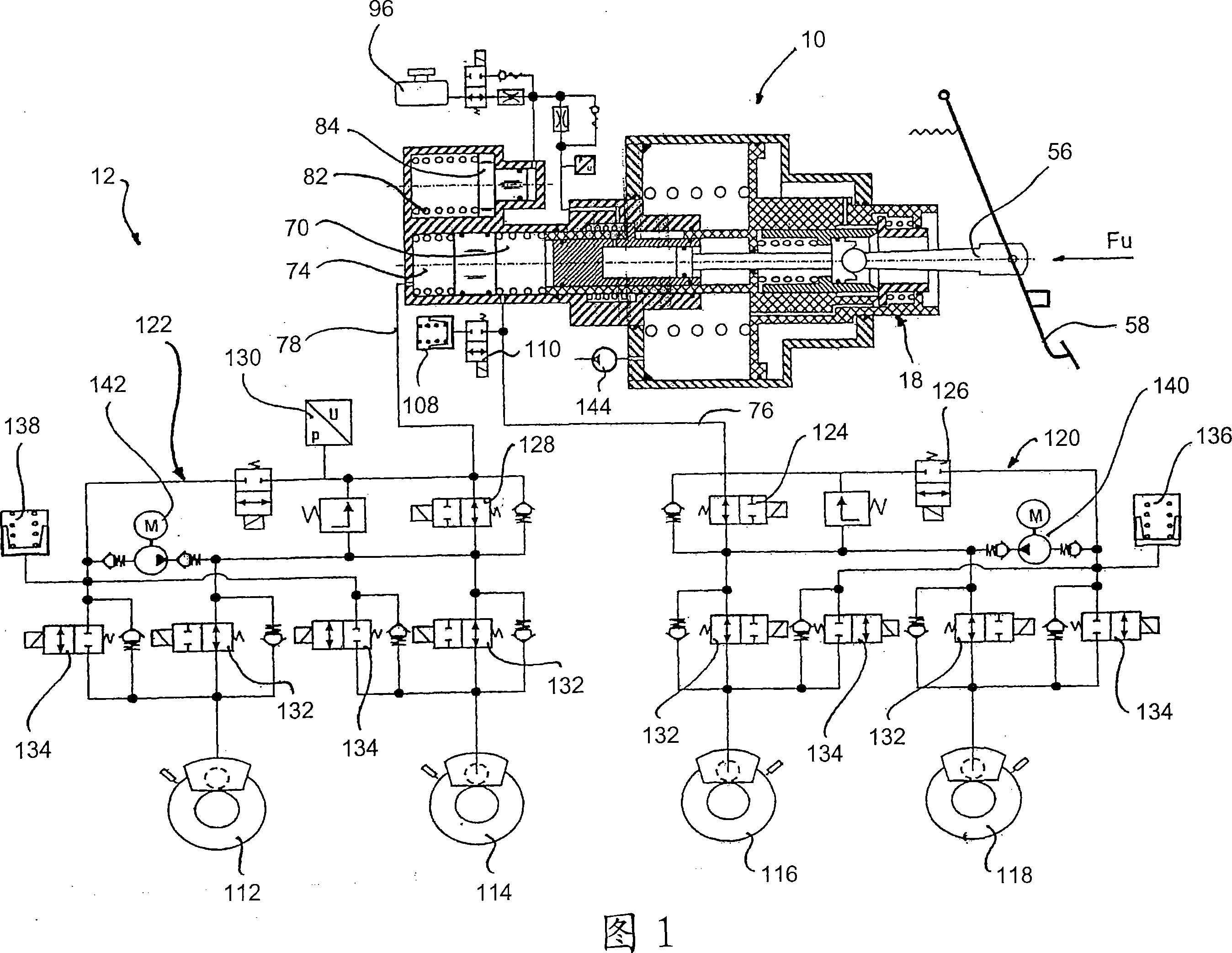
[0032] FIG. 1 shows a brake force generator according to the invention, generally designated 10 , which is integrated in a brake system 12 according to the invention. Before explaining the structure and function of the braking system according to the present invention, first, the braking force generator according to the present invention will be explained in detail.

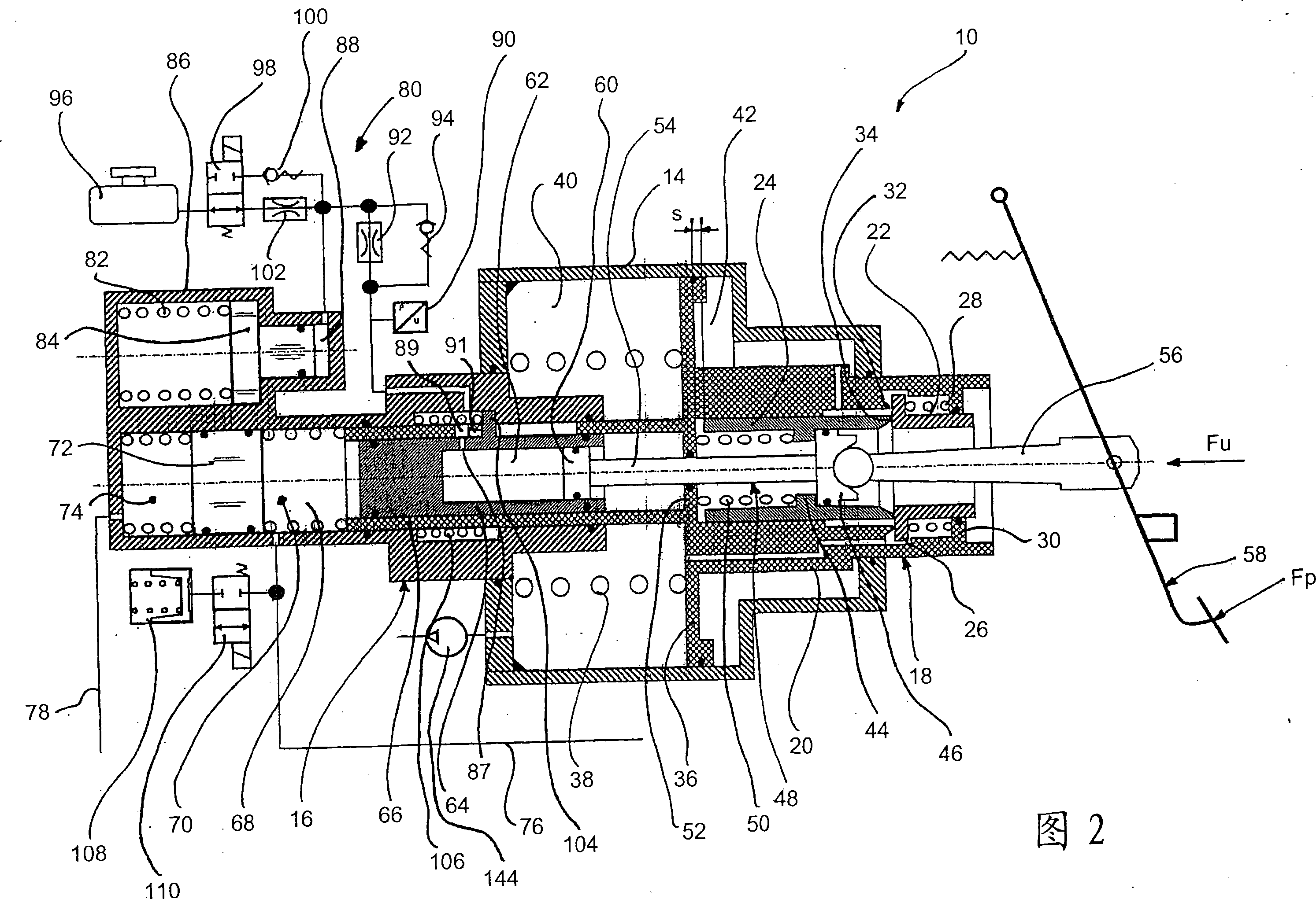
[0033] The brake force generator according to the invention comprises a cylinder housing 14 on the left-hand side in FIG. 2 , which holds a master brake cylinder 16 and into which a control valve 18 is inserted. The control valve 18 includes a control valve housing 20 , a control valve element 22 and a valve sleeve 24 . Formed on the control valve element 22 is a flange 26 against which a pretensioning spring 28 bears. The pretensioning spring 28 is supported at the other end on a collar 30 in which the control valve element 22 is displaceably guided with a sealing effect. On the end of the flange 26 facing awa...


PUM


Abstract

The invention relates to a brake power generator (10) for a hydraulic vehicle braking system (12). Said generator comprises: a power input member (56), which can be or is coupled to a brake pedal (58) and can be displaced in a base housing (14) of the brake power generator (10); a master brake cylinder (16), in which a primary piston (66) is displaceably guided, said primary piston (66) together with the master brake cylinder (16) delimiting a primary pressure chamber (70) for the generation of a hydraulic brake pressure; a pedal counter-force simulation device (80), which can be coupled to the power input member (56); and an actuating force generation unit for exerting an actuating force on the primary piston (66). The brake power generator is characterised in that the pedal counter-force simulation device (80) can be or is fluidically coupled to the power input member (56) and that the actuating force generation unit comprises a control valve (18) and an assembly of chambers, the chamber assembly being configured with a negative pressure chamber (40) and a working chamber (42) that is separated from the negative pressure chamber (40) by a mobile wall (36) and that can be fluidically connected by means of the control valve (18). The control valve (18) can be controlled mechanically by the actuation of the pedal to obtain a pressure differential that determines the actuating force between the working chamber (42) and the negative pressure chamber (40).

Description

technical field [0001] The invention relates to a braking force generator for a hydraulic vehicle braking system and a hydraulic vehicle braking system equipped with such a braking force generator. The brake force generator according to the invention is designed with a force input element which can engage or be coupled to a brake pedal and which is movable within the base housing of the brake force generator, a master brake cylinder in which the master piston is movably guided, and a A pedal reaction force simulation device engaged with the force input element and the actuation force generating device to apply an actuation force on the master piston, wherein the master piston and the master brake cylinder define a master pressure chamber to generate hydraulic brake pressure. Background technique [0002] In braking systems commonly used today, the hydraulic brake pressure necessary to pressurize the wheel brakes on the vehicle is primarily generated by the master brake cylin...

Claims


Application Information

Patent Timeline
Patent Type & Authority Applications(China)
IPC IPC(8): B60T8/40B60T7/04B60L7/26
CPCB60T13/161B60T8/4077B60T13/686B60T13/58
Inventor 彼得·施吕特
Owner LUCAS AUTOMOTIVE GMBH
Features
  • R&D
  • Intellectual Property
  • Life Sciences
  • Materials
  • Tech Scout
  • Unparalleled Data Quality
  • Higher Quality Content
  • 60% Fewer Hallucinations
Learn More