Chair with automatically movable back support

a back support and automatic technology, applied in the field of chairs, can solve the problems of increased fatigue of users, serious influence on the spine, intervertebral disc hernia, etc., and achieve the effects of preventing spinal and musculoskeletal disorders, reducing the cost of storing and moving the chair, and improving convenien

Inactive Publication Date: 2010-09-23
LEE JONG HO
View PDF5 Cites 23 Cited by
  • Summary
  • Abstract
  • Description
  • Claims
  • Application Information

AI Technical Summary

Benefits of technology

[0028]Thanks to the features of the chair having an automatically movable back according to the present invention, advantages are provided in that, regardless of where a user sits on a seat, the back of the chair is automatically moved forwards to correctly support the back of the human body so that a user can sit with his or her back straightened naturally. Therefore, it is possible to sit in a correct sitting posture and protect the spine, so that spinal and musculoskeletal disorders are prevented.
[0029]Also, when compared to the conventional art, convenience is improved and costs for storing and moving the chair can be reduced.

Problems solved by technology

As a consequence, because the back of the chair cannot support the back of the user, the user experiences increased fatigue, and if the incorrect posture becomes a habit, the spine can be seriously influenced, as a result of which intervertebral disc hernia may occur.

Method used


Image

  • Chair with automatically movable back support
  • Chair with automatically movable back support
  • Chair with automatically movable back support

Examples


third embodiment

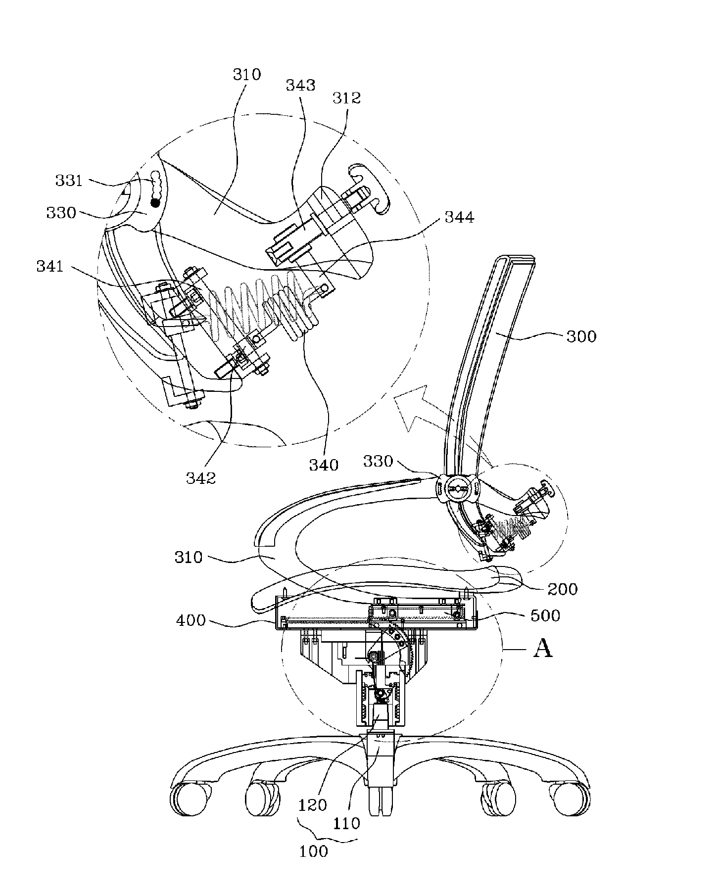
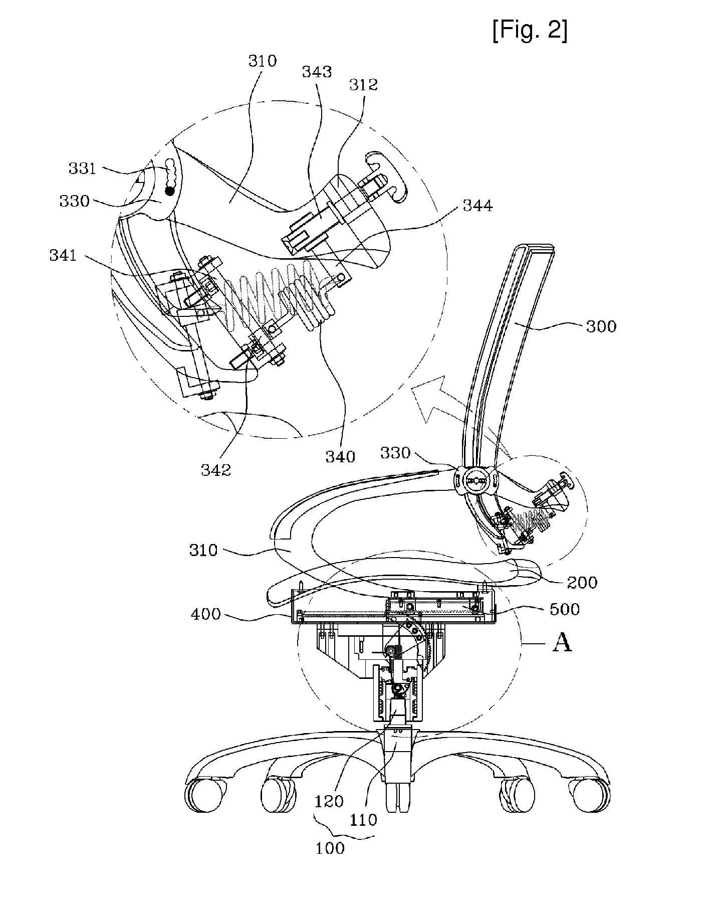
[0085]Hereafter, the chair with an automatically movable back according to the present invention will be described below with reference to FIGS. 2 through 8. FIG. 6 is a front view illustrating a connection shaft, FIG. 7 is a view illustrating the assembled state of an angle adjustment lever, and FIG. 8 is a front view of the angle adjustment lever.

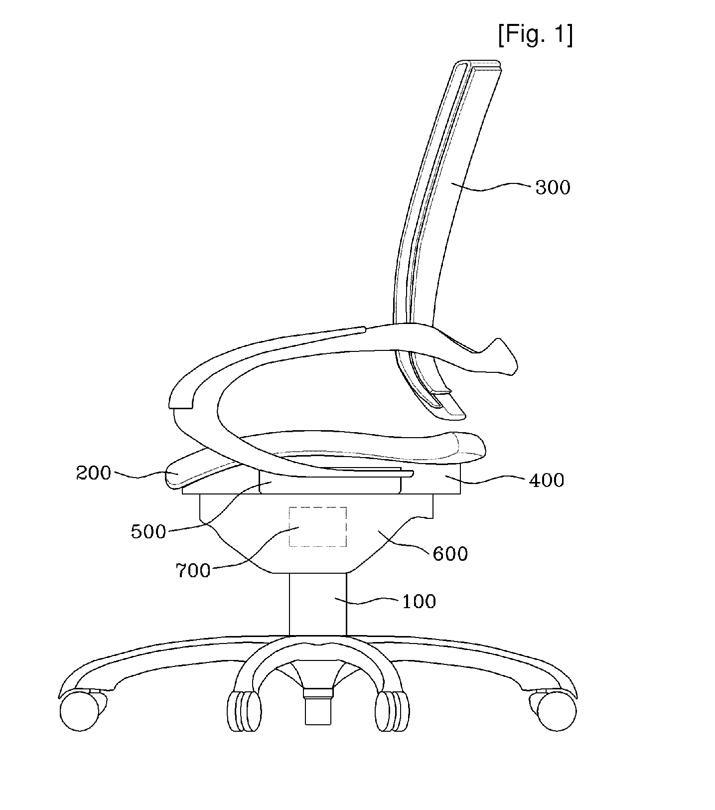
[0086]As can be seen from these drawings, the third embodiment of the present invention is characterized in that, in addition to the horizontal movement of the back 300 and the horizontal movement frame 500, the back 300 can be rotated to enable adjustment of the angle of the back 300.

[0087]In this embodiment, the back 300 of the chair is coupled to the left and right portions of the back frame 310, which is connected with the horizontal movement frame 500 or the tilting frame 820, by means of connection shafts 320 to form a rotatable structure. The connection shafts 320 provide the rotation center of the back 300. In the chair according ...

fourth embodiment

[0101]Hereafter, a chair in accordance with the present invention will be described.

[0102]FIG. 9 is an exploded perspective view illustrating the main parts of a chair in accordance with a fourth embodiment of the present invention, and FIG. 10 is a sectional view illustrating the main parts in an assembled state.

[0103]In the present embodiment, as in the aforementioned embodiment, when a user sits on a seat 200, the back of the chair is moved to be brought into contact with the back of the user. In this regard, the detailed construction of the present embodiment is slightly different from that of the aforementioned embodiments.

[0104]The chair according to this fourth embodiment has, as its main component elements, a base frame 400, a horizontal movement frame 500, a connection housing 900, elastic members ‘S’, and rotation force generation means 700. Specifically, in the present embodiment, as the base frame 400 is moved upwards and downwards relative to the connection housing 900,...

fifth embodiment

[0114]Finally, the present invention will be described. FIG. 11 is a sectional view illustrating a fifth embodiment of the present invention.

[0115]In this embodiment, even though a chair is constructed to have the same construction as the fourth embodiment, when connecting the connection housing 900 to the support 100, a connection bracket 1000 is used as an additional element. The connection bracket 1000 is positioned below the connection housing 900. The connection bracket 1000 is fixed to the support 100, and the connection housing 900 is rotatably connected to the connection bracket 1000. An angle adjustment elastic member 1100 is provided to the connection bracket 1000, and the connection housing 900 is connected to the angle adjustment elastic member 1100. As shown in the drawing, the connection housing 900 can be inclined rearwards with respect to the connection bracket 1000 within a predetermined range, to improve convenience in a situation such as when a user takes a rest.

[...


PUM


Abstract

A chair with an automatically movable back, having a support, and a seat and a back installed on the support. The chair comprises a base frame coupled to a lower surface of the seat in such a way as to define a space between the base frame and the seat; a horizontal movement frame coupled to an upper surface of the base frame to be moved forwards and rearwards, connected at left and right ends thereof to a back frame which in turn is connected with the back of the chair, and having on a lower surface thereof a follower which receives force required for forward and rearward movement; a vertical movement frame which has an upper surface which is connected to the lower surface of the base frame and a lower surface which is connected to the support, and which is coupled to the support such that the vertical movement frame can slide upwards and downwards with respect to the support; and rotation force generation means installed in the vertical movement frame to transmit rotation force generated by upward and downward movement of the vertical movement frame to the follower such that the horizontal movement frame can be moved forwards and rearwards.

Description

TECHNICAL FIELD[0001]The present invention relates to a chair having a seat and a back, and more particularly, to a chair having an automatically movable back wherein the back of the chair can be automatically moved by a user's weight to properly support the back of the user even when the user sits on a seat without bringing his or her back into contact with the back of the chair, thereby allowing the user to have a correct sitting posture.BACKGROUND ART[0002]In general, a chair has a back for supporting the back of a user who sits on the chair to help the user to rest in a comfortable posture and protect the spine of the user.[0003]It is generally not considered correct posture to sit by placing the hips on the front portion of the seat. Therefore, only when the hips are placed on the very rear portion of the seat and the back of the user is brought into close contact with and supported by the back of the chair can the spine of the user be protected from bending.[0004]Hence, the ba...

Claims


Application Information

Patent Timeline
Patent Type & Authority Applications(United States)
IPC IPC(8): A47C7/46
CPCA47C7/54A47C7/40A47C7/46
Inventor LEE, JONG HO
Owner LEE JONG HO
Why Eureka
Try Eureka