
Enhanced permanent magnet electromagnetic actuator for an electronic valve actuation system of an engine

a technology of electromagnetic actuator and permanent magnet, which is applied in the direction of machines/engines, non-mechanical valves, magnetic bodies, etc., can solve the problems of reducing engine peak power, difficult to accurately control the armature and/or seat landing speed, and creating noise and wear, etc., to achieve increased force output, reduce height requirements, and reduce resistance

Inactive Publication Date: 2007-07-31
FORD GLOBAL TECH LLC
View PDF12 Cites 24 Cited by
  • Summary
  • Abstract
  • Description
  • Claims
  • Application Information

AI Technical Summary

Benefits of technology

[0005]Third, the power consumption of an electric valve actuation (EVA) system can have an impact on vehicle fuel economy, engine peak power, and the size / cost of the electrical power supply system. Therefore, reducing power consumption of the actuator, without sacrificing performance, can be advantageous.
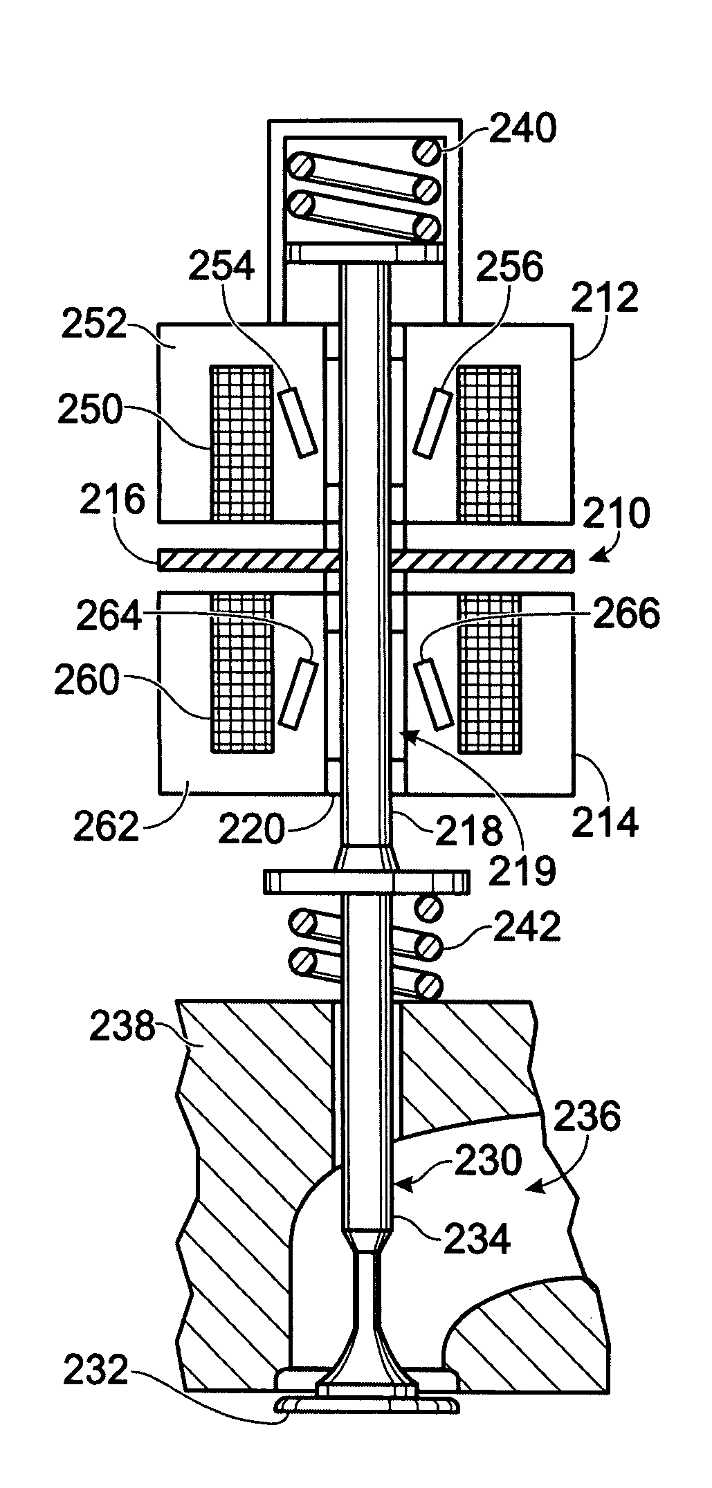
[0013]In this way, there may be increased space for the permanent magnet (on the sides of the coils), and the actuator height is not required to be increased (although it can be, if desired). Additionally, since coil space is not necessarily limited by height; increased coil resistance can be avoided or reduced.
[0015]In one specific example, such an approach can be used so that the area of the permanent magnet surface contacting the core is larger than the center pole area facing the armature. As a result, the flux density in the center pole surface may be higher than the flux density in the permanent magnet material's surface, which is limited by the permanent magnet material property. Further, since the magnetic force is proportional to the square of the flux density, this embodiment can increase (significantly in some examples) the force, without necessarily increasing the height of the actuator. And since the permanent magnet is in the path of the flux produced by the current, in one example, the actuator can have a low dF / dx and dF / di (rate of change of force with respect to changes in current), which can be beneficial for landing speed control. Further, the recesses can be used to affect the flux leakage to provide even further improvements. Note that the recess can be used with an angled permanent magnet, or non-angled permanent magnets.
[0016]As such, various advantages can be achieved in some cases, such as decreased resistance, decreased height requirements, and increased force output, while maintaining reduced dF / dx and dF / di (which can help valve landing control).

Problems solved by technology

First, valve landing during opening and closing of the valve can create noise and wear.
As such, it can be difficult to accurately control the armature and / or seat landing velocity.
In other words, due to limited force producing capability, the transition time of some previous systems may be too slow, and therefore result in reduced engine peak power.
Third, the power consumption of an electric valve actuation (EVA) system can have an impact on vehicle fuel economy, engine peak power, and the size / cost of the electrical power supply system.
As a first example, such a configuration can result in increased coil resistance or actuator height requirements.
As a second example, the flux enhancing effect may also be limited by actuator height.
In other words, the amount of space below the coils available for the permanent magnet is limited due to packaging constraints, for example.
Therefore, while some flux enhancement may be possible, it comes at a cost of (as is limited by) height restrictions.
Still another potential disadvantage with the approach of JP 2002130510A is that it can be more difficult to manufacture due to the peak of the V in FIG. 9.
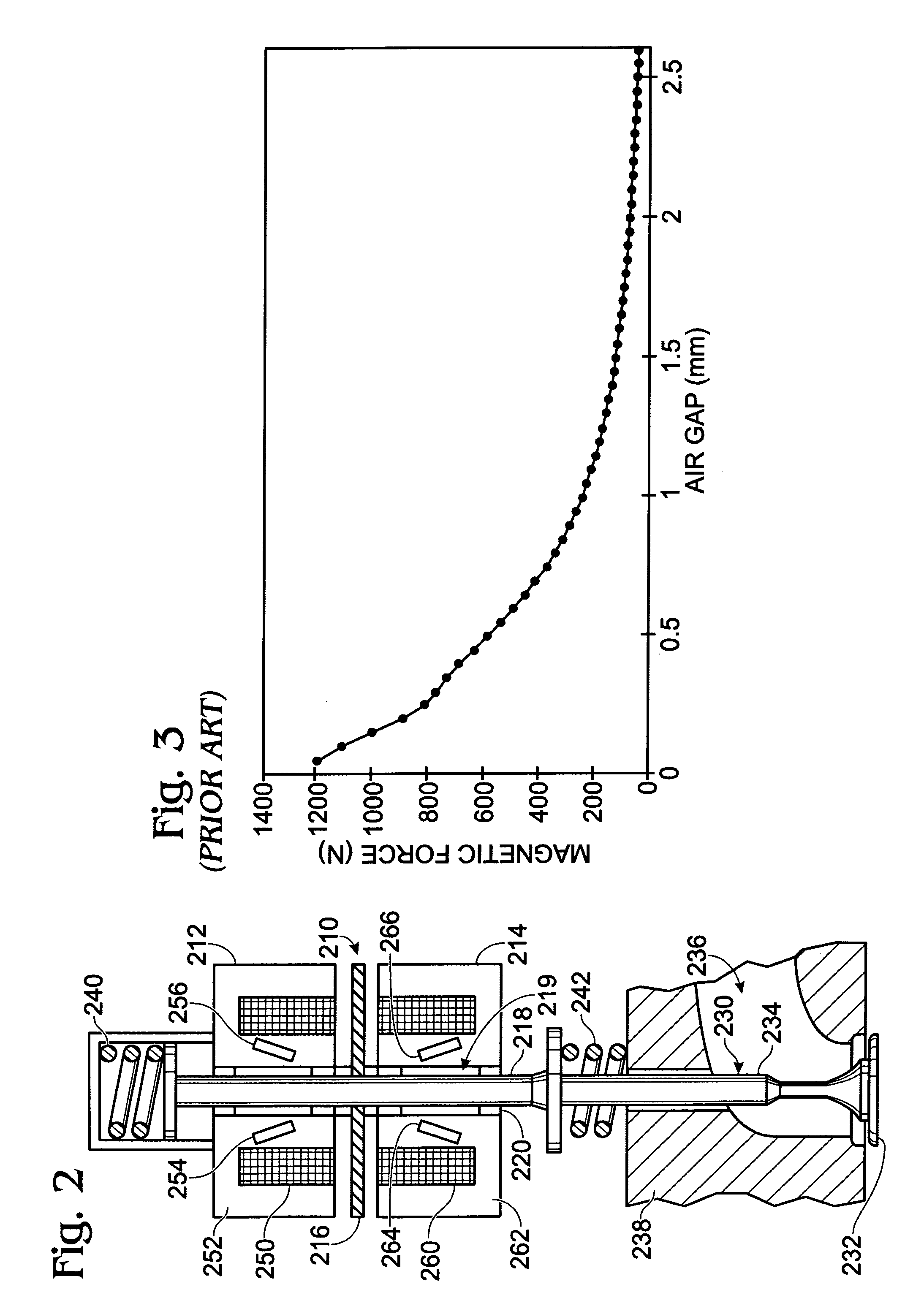
However, the inventors herein have also recognized that while such an approach may produce a low dF / dx, it still produces low magnetic force due to the magnetic strength limit of the permanent magnet material.
As a result, the flux density in the center pole surface may be higher than the flux density in the permanent magnet material's surface, which is limited by the permanent magnet material property.

Method used


Image

  • Enhanced permanent magnet electromagnetic actuator for an electronic valve actuation system of an engine
  • Enhanced permanent magnet electromagnetic actuator for an electronic valve actuation system of an engine
  • Enhanced permanent magnet electromagnetic actuator for an electronic valve actuation system of an engine

Examples


example a

[0112 shows recess 3870 at the outer edge of the side poles, which is similar to recess 3690 of FIG. 36. Example B shows recess 3872 at the interior edge of the side poles. Example C shows a combination of recesses 3872 and recess 3874 on the exterior edges of the center pole, while Example D shows only recess 3874 on the edges of the center pole. Example E shows recess 3876 in the center region on the armature end of the center pole, similar to recess 3680. Example F shows multiple recesses 3876 (three) evenly spaces along the armature end edge of the center pole. Example G shows multiple recesses 3876 (three), one placed in the center region on the armature end edge of each of the two side poles and the center pole. Example H shows multiple recesses 3878 in the shape of a rectangular notch at each corner of the armature edge of the poles and the coil cavity. Example I shows a half-circle shaped recess 3880 in the center region of the armature edge of the center pole. Recess 3880 c...


PUM


Abstract

A valve actuator for an internal combustion engine is described having a core having a wound coil located therein, said core further having at least one permanent magnet located at least partially inside or outside said coil and positioned at an angle relative to a direction of movement of an armature. Further, various recesses, indentations, chamfers, bevels, and / or depressions may be included to affect flux leakage, and / or force generation.

Description

CROSS-REFERENCE TO RELATED APPLICATIONS[0001]The present application is a continuation-in-part of, and claims priority to, U.S. patent application Ser. No. 10 / 811,085, filed Mar. 25, 2004, titled “PERMANENT MAGNET ELECTROMAGNETIC ACTUATOR FOR AN ELECTRONIC VALVE ACTUATION SYSTEM OF AN ENGINE” and having the same assignee as the present application, the entire contents of which are hereby incorporated by reference.FIELD [0002]The field of the disclosure relates to electromechanical actuators coupled to cylinder valves of an internal combustion engine, and more particularly to a dual coil valve actuator.BACKGROUND AND SUMMARY [0003]Electromechanical valve actuators for actuating cylinder valves of an engine have several system characteristics to overcome. First, valve landing during opening and closing of the valve can create noise and wear. Therefore, valve landing control is desired to reduce contact forces and thereby decrease wear and noise. However, in some prior art actuators, t...

Claims


Application Information

Patent Timeline
Patent Type & Authority Patents(United States)
IPC IPC(8): F01L9/04F01L9/20B05B9/00F01L1/34
CPCF01L9/04H02K3/28F01L2009/0436F01L2009/0448H02K3/34F01L2009/2136F01L2009/2148F01L9/20
Inventor LIANG, FENGDEGNER, MICHAEL
Owner FORD GLOBAL TECH LLC
Learn More