Steering control device

a control device and steering technology, applied in the direction of steering initiation, special purpose vessels, vessel construction, etc., can solve the problems of reduced steering reaction force of reaction force motor b>4/b>, reduced steering reaction force, and disadvantageous effects of vehicle manufacturing cost, etc., to achieve effective and rational treatment

Inactive Publication Date: 2008-02-05
JTEKT CORP
View PDF19 Cites 23 Cited by
  • Summary
  • Abstract
  • Description
  • Claims
  • Application Information

AI Technical Summary

Benefits of technology

[0044]According to the above described first aspect of the present invention and its various conf

Problems solved by technology

As a result of this problem, in the case of the conventional method, compact and lightweight manufacture of the vehicle wheel steering actuator (the vehicle wheel steering motor 6) is hindered, and thus when the above described conventional method is adopted, vehicle manufacturing cost, vehicle design flexibility, and ease of vehicle maneuver, and the like, are all disadvantageously aff

Method used


Image

  • Steering control device
  • Steering control device
  • Steering control device

Examples


first embodiment

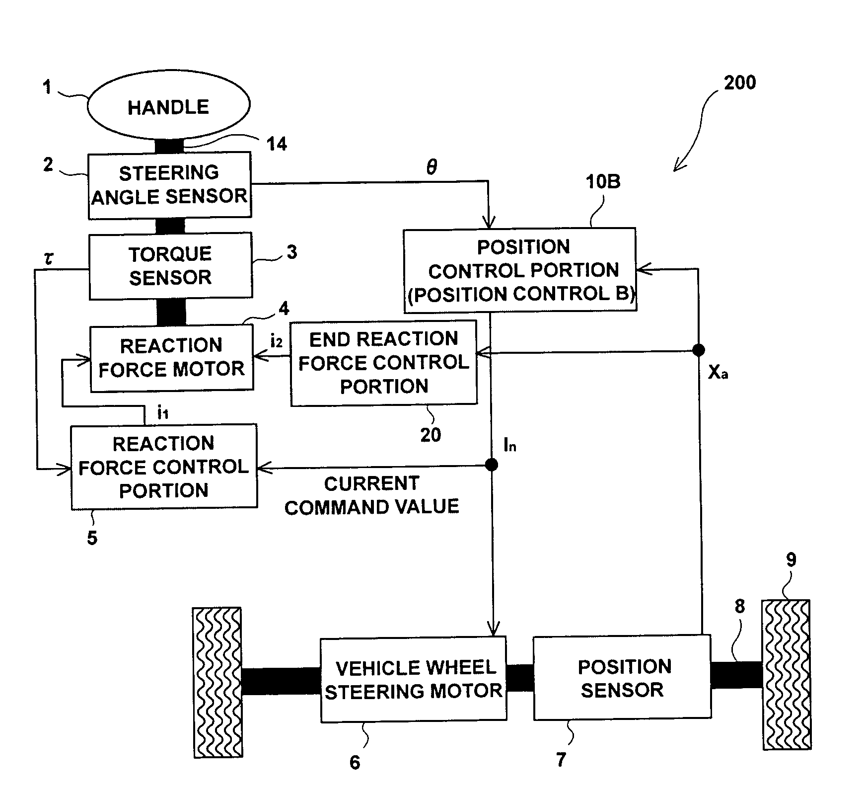
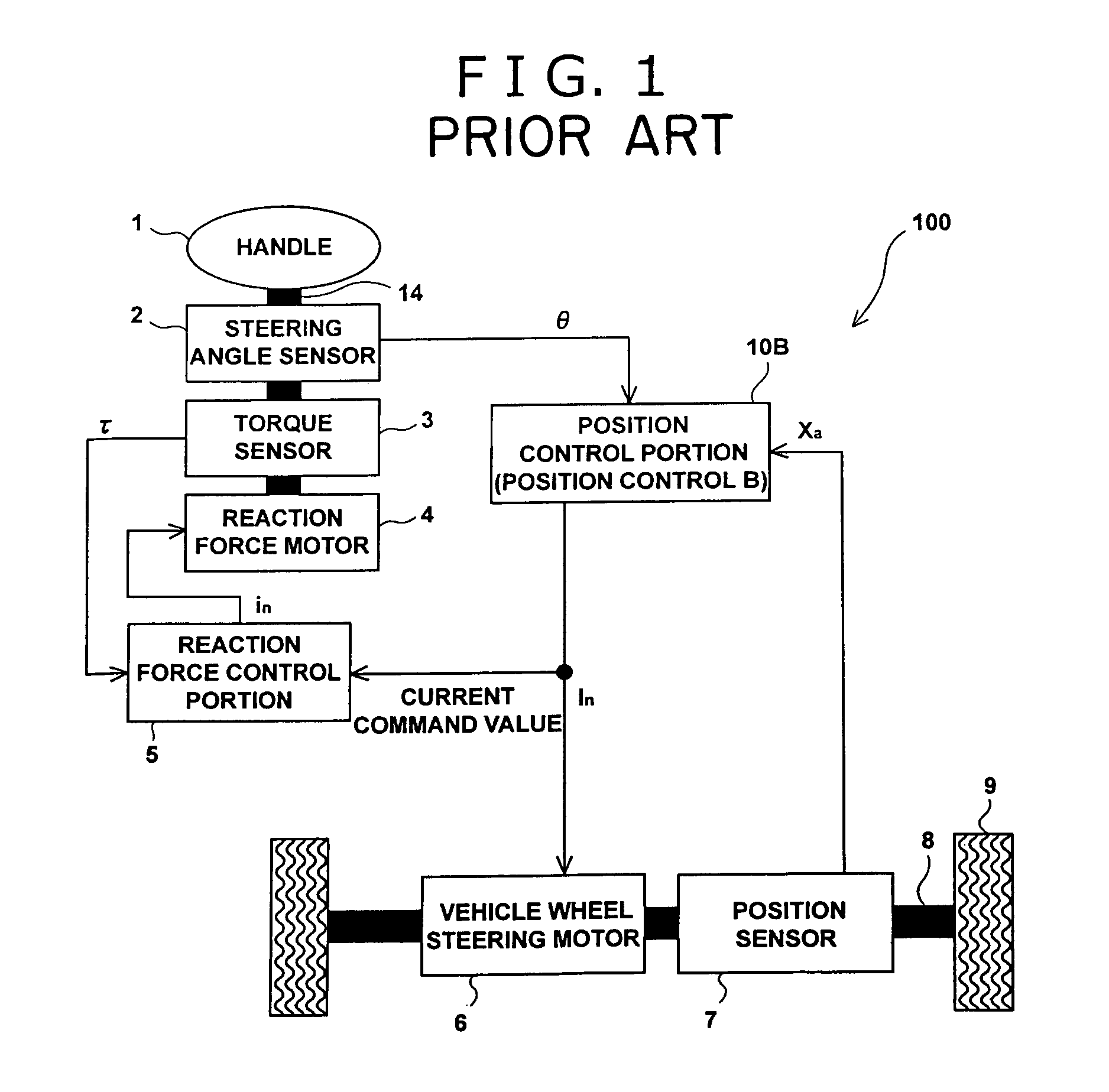
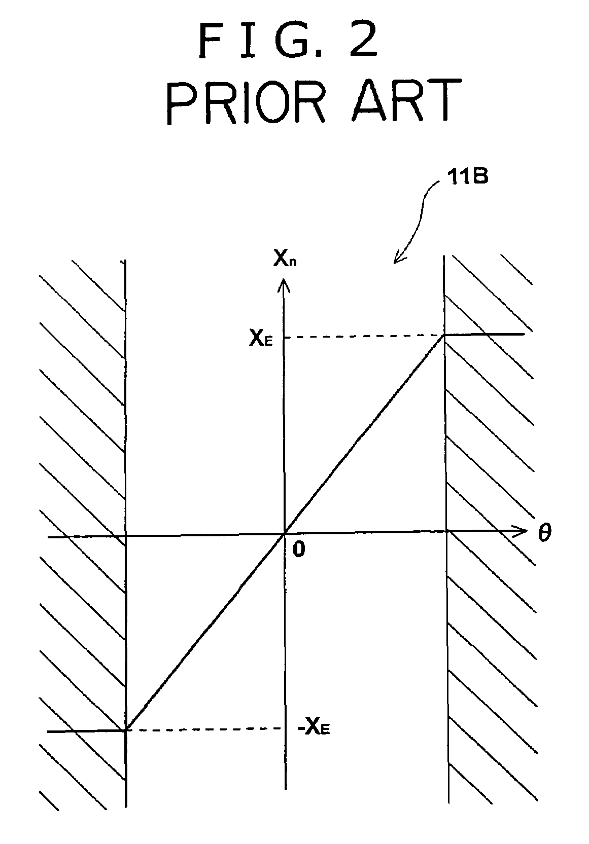
[0059]FIG. 3 is a control block diagram showing a control method of a steering control device 200 of a first embodiment of the present invention. In this steering control device 200, like the previously described steering control device 100, the position control portion 10B of FIG. 1 is configured using the steering change amount command value calculation portion 11B of FIG. 2, instead of by the steering change amount command value calculation portion 11A of FIG. 13. The position control (the position control B) of the vehicle wheel steering shaft 8 is executed by operations of the steering change amount command value calculation portion 11B and the PID control portion 12.

[0060]As stated previously, the position control portion 10B of the steering control device 200 (FIG. 3), like the steering control device 100, is configured from the steering change amount command value calculation portion 11B of FIG. 2, instead of by the steering change amount command value calculation portion 11...

second embodiment

[0068]FIG. 5 is a control block diagram showing a control method of a steering control device 300 of a second embodiment of the present invention. This steering control device 300 is configured by making a number of modifications to the structure of the steering control device 200 of the first embodiment. It should be noted that, fundamentally, structural members that are not specifically referred to below have the same structure as equivalent members of the steering control device 200.

[0069]Hereinafter, a detailed explanation will be given of the structure, control procedure, operation, effects, and the like, of the steering control device 300 of the second embodiment; the characterizing portions of the steering control device 300 will be focused on in this explanation.

[0070]The steering control device 300 of the second embodiment most significantly differs from the steering control device 200 with respect to the fact that, as the end-of-movement reaction force generation unit, the...

third embodiment

[0104]A third embodiment has the structure of the previously described second embodiment with a number of portional modifications. Hereinafter, a concrete explanation will be given of other structural members (i.e., a steering change amount command value calculation portion 11C) related to the steering change amount command value calculation portion 11B of the steering control device 300.

[0105]FIG. 11 illustrates a calculation method of the steering change amount command value calculation portion 11C according to the third embodiment. The vertical axis divisions XE1 and XE3 indicate the upper limit value (XE) of the permissible range of respective steering change amounts corresponding to vehicle speed v1 and v3 of FIG. 9. More specifically, even in the case that the steering angle θ changes significantly, the steering control amount command value Xn does not exceed the upper limits (XE1, XE3) at the respective vehicle speeds. Moreover, with the third embodiment, the upper limit (XE2...


PUM


Abstract

A steering control device (200) is provided with a end-of-movement reaction force generation unit (an end reaction force control portion (20)). An end reaction force generating current i2 which act as return a handle toward a straight-ahead position is rapidly generated in the vicinity of an upper and a lower limit of a vehicle wheel steering range. For example, a reaction force motor (4) may be additionally commanded using a newly generated command current i2. Accordingly, an output torque of the reaction force motor (4) becomes proportional to a new command value in of an Equation in=i1+i2, where i1 is a current command of a reaction force control portion (5). As a result of configuring the end-of-movement reaction force generation unit is this manner, for example, it is possible to generate a virtual contact resistance force (a steering reaction force) for a steering angle θ without causing heat build-up, or the like, of a motor, when no physical limit (an end-of-movement of contact point) is provided for a rotation range of a steering wheel (handle).

Description

INCORPORATION BY REFERENCE[0001]The disclosure of Japanese Patent Application No. 2002-298664 filed on Oct. 11, 2002 including the specification, drawings and abstract is incorporated herein by reference in its entirety.BACKGROUND OF THE INVENTION[0002]1. Field of the Invention[0003]The present invention relates to a steering control device that is provided with a steering wheel steering mechanism having a steering actuator that imparts a steering reaction force to a steering wheel, and a vehicle wheel steering mechanism having a vehicle wheel steering actuator that drives a vehicle wheel steering shaft.[0004]The present invention can be effectively applied to various types of steering control device that are mounted in a vehicle, such as, for example, a so-called steer-by-wire system or a so-called variable gear ratio system.[0005]2. Description of the Related Art[0006]As an example of a conventional steer-by-wire system, art such as that disclosed in Patent Document 1 and Patent D...

Claims


Application Information

Patent Timeline
IPC IPC(8): B62D5/00B62D5/04B62D6/00B63G8/20B62D113/00B62D119/00
CPCB62D5/0469B62D6/008
Inventor SAKAI, ATSUO
Owner JTEKT CORP
Why Eureka
Try Eureka