Vehicle engine control device

a technology of engine control and control device, which is applied in the direction of electric control, ignition automatic control, instruments, etc., can solve the problems of inability to obtain sufficient driving force, inability to escape driving, and ineffective operation of accelerator pedal

Inactive Publication Date: 2004-01-01
MITSUBISHI ELECTRIC CORP
View PDF0 Cites 87 Cited by
  • Summary
  • Abstract
  • Description
  • Claims
  • Application Information

AI Technical Summary

Problems solved by technology

The safety throttle valve opening degree is set to a valve opening position slightly larger than an idling valve opening position, and in escape driving at the time of the occurrence of an abnormality, an operation of an accelerator pedal becomes ineffective, and one pedal operation is carried out in which vehicle speed is adjusted while the depression degree of a brake pedal is adjusted.
However, if the safety throttle valve opening degree is small, there is a problem that even if the brake is released, a sufficient driving force can not be obtained, and climbing escape driving can not be carried out.
On the contrary, if the safety throttle valve opening degree is excessively large, a dangerous state occurs in which even if the brake pedal is sufficiently depressed, it is difficult to stop the vehicle.
Further, it is also necessary to consider such a problem that a default return has not been correctly carried out because of a mechanical abnormality in the throttle valve opening degree control.
However, even by the driving function using the depression of the accelerator pedal, when the throttle valve opening degree is small, a sufficient vehicle speed can not be obtained, and this driving function using the depression of the accelerator pedal is absolutely a minimum driving function for the purpose of escaping from the site.
Accordingly, in the escape driving control illustrated in FIG. 12(a), even if the upper limit rotational speed of the engine is regulated to the threshold or lower, an actual throttle valve opening degree is uncertain, and it is a problem that the driving torque of the engine is changed by the magnitude of the throttle valve opening degree, and there is a danger that when the throttle valve opening degree is large, braking by the brake pedal becomes difficult.
To this end, if the upper threshold by the upper limit rotation threshold setting means 2c is made low, a sufficient driving force can not be obtained, and especially in the case where the throttle valve opening degree is small, there is a problem that the climbing escape running becomes quite impossible.
The control of the prior art 3 has a feature that the escape driving is carried out by normal two-pedal driving and there is no feeling of wrongness, however, there is a problem that the objective throttle valve opening degree is suppressed so that the driving torque of the engine is decreased, and sufficient climbing performance can not be obtained.
Particularly, there are problems that a method of specifying a non-defective unit in the abnormality judgment means of the APS or the TPS is not used, and suppression of the objective opening degree is not carried out rationally and quantitatively.
However, it is not indicated that what escape driving is carried out in the case where the accelerator position sensor is inferior, and especially in the case where the accelerator pedal is returned, if the detection output voltage of the accelerator position sensor is excessive, there is also a case where a dangerous state occurs in which it is difficult to make a stop by a brake pedal.
The escape driving means according to the prior art 5 as described above is escape driving means in the case where both the accelerator position sensor and the throttle position sensor are normal, and the control of the engine rotational speed is also of the open loop control system, and therefore, there is a problem that for example, an engine rotational speed when the accelerator pedal is returned is much changed by the magnitude of the throttle valve opening degree.
However, there is a problem that a sufficient engine output adjustment can not be made by only the adjustment of the fuel injection amount and the ignition advance.
What is disclosed in the prior art 7 is also the control of decreasing cylinders in the open loop system, and there is a problem that for example, the engine rotational speed when the accelerator pedal is returned is much changed by the magnitude of the throttle valve opening degree.
However, there is a problem that a sufficient output adjustment of an engine can not be made only by the adjustment of the fuel injection amount and the ignition advance.
In the above-described prior art, there are problems that the abnormality detection means relating to the added electric throttle control function and the escape driving control corresponding to this are not systematic, and even in the case where the actuator system and the accelerator position sensor are normal, the generated torque of the engine at the time of escape driving is suppressed and climbing performance is lowered, or in the case where the actuator system or the accelerator position sensor is abnormal, braking by a brake pedal becomes difficult, or on the contrary, it becomes impossible to secure a sufficient driving force.

Method used


Image

  • Vehicle engine control device
  • Vehicle engine control device
  • Vehicle engine control device

Examples


embodiment 1

[0082] Hereinafter, a structure of an engine control device of this invention will be described.

[0083] (11) Description of the Whole Structure of the Embodiment 1

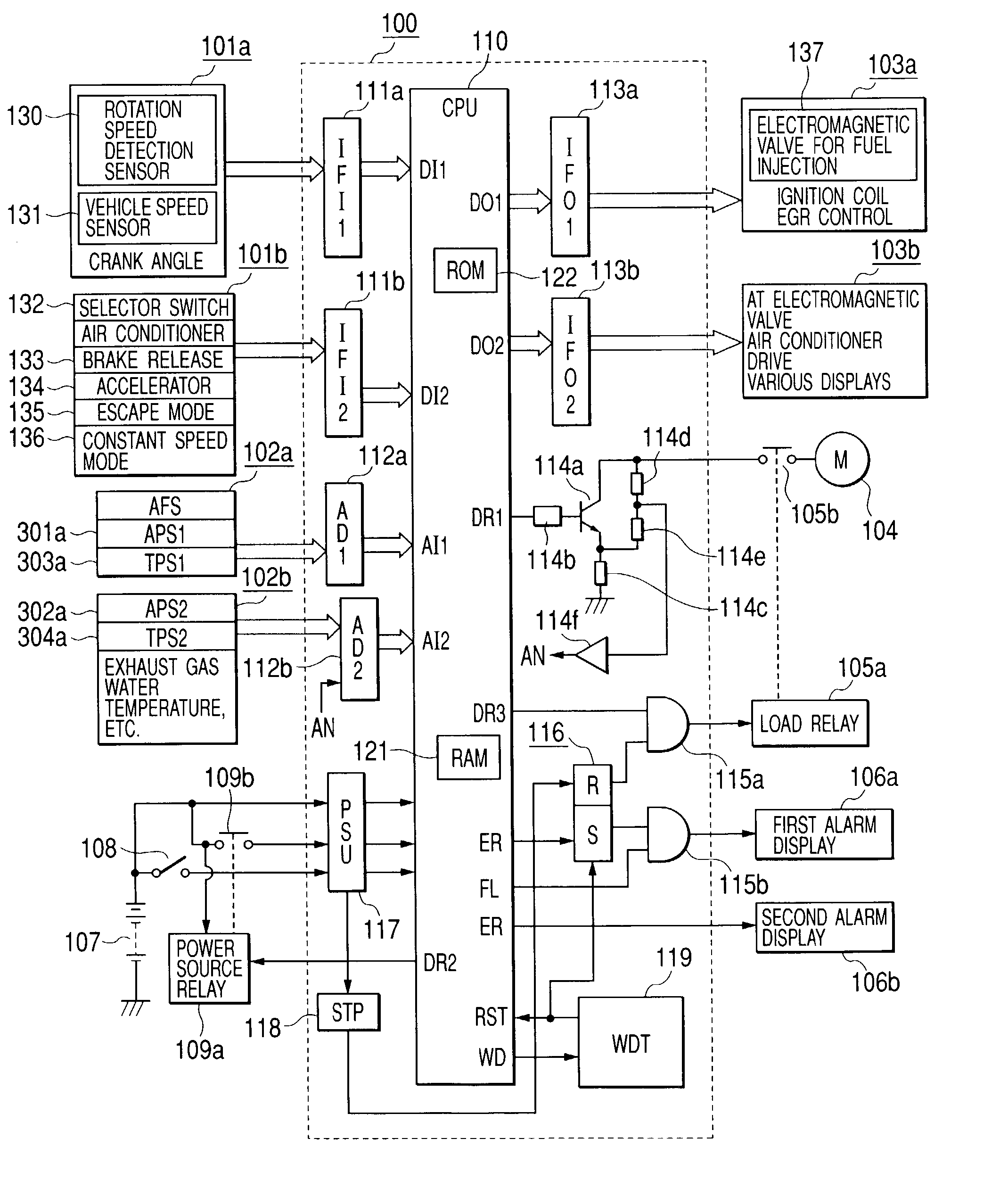
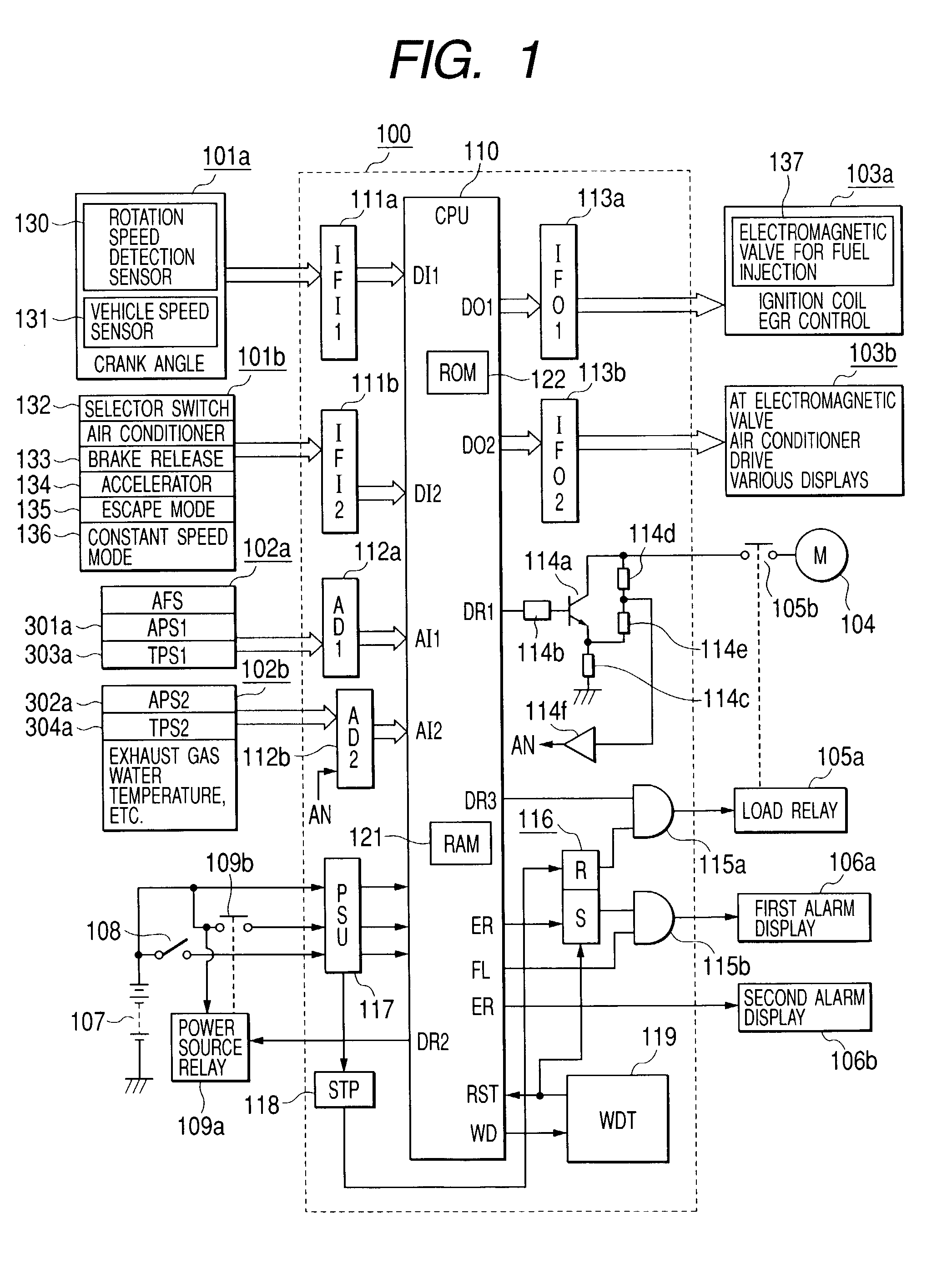
[0084] First, a description will be given of FIG. 1 showing the whole structure of the embodiment 1.

[0085] A vehicle engine control device 100 shown in FIG. 1 is constituted by an electronic substrate contained in a not-shown sealed receptacle and is mainly composed of a microprocessor 110. This vehicle engine control device 100 is connected to an external input / output equipment through a not-shown connector.

[0086] The engine control device 100 includes plural input / output circuits disposed around the microprocessor 110. A first digital input sensor group 101a, a second digital input sensor group 101b, a first analog input sensor group 102a, and a second analog input sensor group 102b are provided at an input side of the microprocessor 110.

[0087] The first digital input sensor group 101a includes a rotation detection sensor...

embodiment 2

[0263] Embodiment 2

[0264] Next, embodiment 2 of a vehicle engine control device according to this invention will be described.

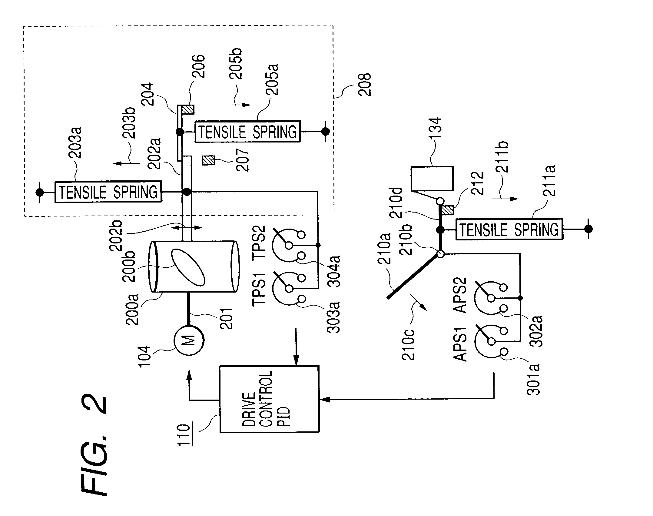
[0265] In this embodiment 2, the non-defective judgment of the accelerator position sensors PAS1 and APS2 and the throttle position sensors TPS1 and TPS2 in the embodiment 1 is further improved. This embodiment 2 is constructed such that the structure and operation of the embodiment 1 are adopted as they are, and in addition to those, an improved non-defective unit judgment operation is carried out. Specifically, the embodiment 2 adopts the whole structure shown in FIG. 1, the structure of the intake throttle portion shown in FIG. 2, the slight abnormality escape running control block shown in FIG. 3, the severe abnormality escape running control block shown in FIG. 4, the abnormality detection flowchart of the accelerator position sensor shown in FIG. 5, the abnormality detection flowchart of the throttle position sensor shown in FIG. 6, and the upper limit ...

embodiment 3

[0282] Embodiment 3

[0283] Next, embodiment 3 of a vehicle engine control device according to this invention will be described.

[0284] This embodiment 3 further adds a slight abnormality escape running mode to the embodiment 1. This embodiment 3 adopts the structure and operation of the embodiment 1 as they are, and further includes the slight abnormality escape running mode. Specifically, the embodiment 3 adopts the whole structure shown in FIG. 1, the structure of the intake throttle portion shown in FIG. 2, the slight abnormality escape running control block shown in FIG. 3, the severe abnormality escape running control block shown in FIG. 4, the abnormality detection flowchart of the accelerator position sensors shown in FIG. 5, the abnormality detection flowchart of the throttle position sensors shown in FIG. 6, and the upper limit rotational speed setting flowchart shown in FIG. 7 as they are, and in addition to those, this embodiment is constructed to execute a slight abnormali...


PUM


Abstract

Escape running performance at the time of the occurrence of an abnormality in an electronic throttle control system is improved. At the time of the occurrence of a severe abnormality, an abnormality storage element is operated, and an electric supply load relay of a throttle valve driving motor is de-energized to return a throttle valve to the default, and further, an alarm display is actuated, and an upper limit engine rotational speed is suppressed by control of a fuel injection valve, and escape running is carried out. As a suppression rotational speed, a lower limit threshold at a stop, a rotational speed substantially in proportion to the output of an accelerator position sensor, a rotational speed substantially in inverse proportion to the output of a throttle position sensor, or a default threshold rotational speed is selected, and multiple escape running can be carried out.

Description

[0001] 1. Field of the Invention[0002] The present invention relates to a vehicle engine control device, and particularly to a vehicle engine control device in which the safety of additional functions and the performance of escape driving at an emergency are improved in an engine control unit (ECU) for carrying out ignition control of an engine, fuel injection control and the like, especially in a compound type ECU added with, as additional functions, an electronic throttle control function for controlling an opening degree of an intake throttle valve by a driving motor.[0003] 2. Description of the Related Art[0004] An engine control unit (hereinafter referred to as an ECU) using a microcomputer is widely used to carry out ignition control and fuel injection control of a vehicle engine. Recently, a compound type ECU added with, as additional functions, an electronic throttle control function for controlling the opening degree of a throttle valve by an electric motor is proposed and ...

Claims


Application Information

Patent Timeline
Patent Type & Authority Applications(United States)
IPC IPC(8): F02D9/02F02P5/15F02D11/10F02D17/04F02D31/00F02D41/22F02D45/00
CPCF02D11/107F02D2041/227F02D31/009
Inventor HASHIMOTO, KOHJINAKAMOTO, KATSUYA
Owner MITSUBISHI ELECTRIC CORP
Why Eureka
Try Eureka