Control apparatus and control method for vehicular drive system

A technology for control devices and vehicle drives, applied in transmission devices, power devices, electric power devices, etc., can solve problems such as inability to properly control the speed of the first electric motor

Inactive Publication Date: 2008-07-02
TOYOTA JIDOSHA KK
View PDF1 Cites 8 Cited by
  • Summary
  • Abstract
  • Description
  • Claims
  • Application Information

AI Technical Summary

Problems solved by technology

At this time, as described above, if the charging or discharging of the power storage device is restricted, it may not be possible to appropriately control the rotational speed of the first electric motor when a shift is performed in the shifting portion during motor running.

Method used


Image

  • Control apparatus and control method for vehicular drive system
  • Control apparatus and control method for vehicular drive system
  • Control apparatus and control method for vehicular drive system

Examples


Embodiment Construction

[0050] In the following description and drawings, the invention will be described in detail in terms of exemplary embodiments.

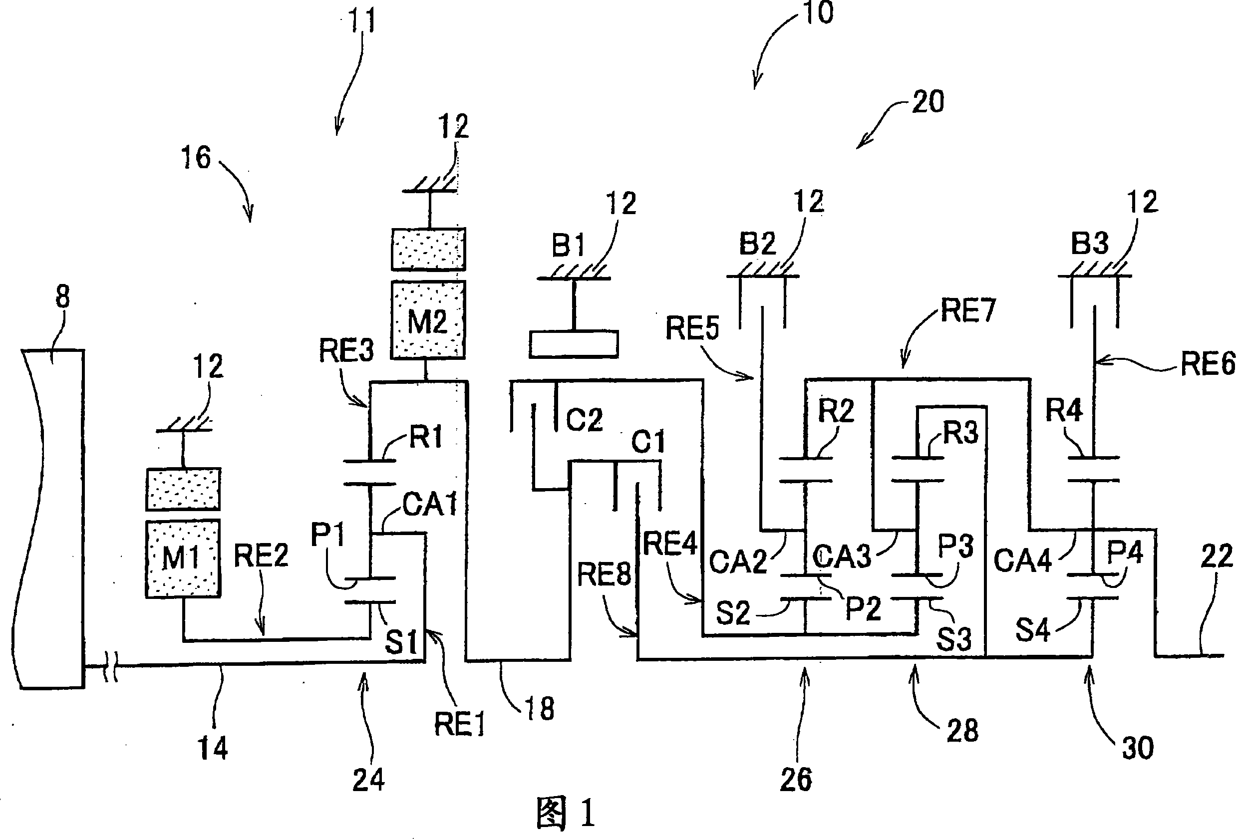
[0051] FIG. 1 is a schematic diagram of a transmission mechanism 10 constituting a part of a drive system of a hybrid vehicle to which the present invention is applicable. In FIG. 1 , a transmission mechanism 10 includes, in sequence (in series), an input shaft 14 , an electric differential portion (hereinafter simply referred to as “differential portion”) 11 , an automatic transmission portion 20 , and an output shaft 22 . The input shaft 14 is an input rotary member arranged on a common shaft inside the transmission case 12 , which is a non-rotational part mounted on a vehicle body (hereinafter, the transmission case 12 is simply referred to as "case 12"). The differential portion 11 is a continuously variable transmission portion connected either directly to the input shaft 14 or indirectly connected to the input shaft 14 through a pulsation absor...


PUM


Abstract

In a control apparatus of a vehicular drive system, a charging / discharging-restricted shift control apparatus makes a determination to perform a shift in a shifting portion such that less power is charged to a power storage device or discharged from a power storage device when charging or discharging of the power storage device is restricted than when charging or discharging of the power storage device is not restricted.

Description

technical field [0001] The present invention relates to a control device and a control method for a vehicle drive system equipped with: i) an electric differential portion having a differential mechanism capable of differential operation (differential action); and ii ) is provided in the transmission section in the power transmission path from the electric differential section to the drive wheels. More specifically, the present invention relates to a control device and a control method for a vehicle drive system when charging or discharging of a power storage device is restricted. Background technique [0002] A known control device for a vehicle drive system includes an electric differential portion and a transmission portion. The electric differential section includes a differential mechanism having three elements, namely, a first element connected to the engine, a second element connected to the first electric motor, and a third element connected to the transmission memb...

Claims


Application Information

Patent Timeline
Patent Type & Authority Applications(China)
IPC IPC(8): B60W10/10B60W10/26B60W30/20F16H61/04F16H61/32F16H3/72B60K6/365B60K6/445B60K6/543B60K6/547B60L50/16B60W10/04B60W10/06B60W10/08B60W10/105B60W10/11B60W10/113B60W20/00F16H61/10F16H61/68F16H61/684F16H61/688F16H63/50
CPCY02T10/6239Y02T10/6217B60W10/115B60W2520/10F16H61/686F16H2200/0043F16H3/728B60K6/547F16H2037/0873B60K6/365B60K6/445B60W20/00B60L2270/145F16H2200/2043F16H61/0213Y02T10/70B60K1/02B60L2250/30B60L11/14F16H2200/2012Y02T10/7077B60L11/123B60W10/26F16H2061/0227B60K6/40B60L2220/14B60L50/61B60L50/16Y02T10/62Y02T10/7072B60W2510/0676B60W20/13B60W10/08
Inventor 柴田宽之松原亨田端淳
Owner TOYOTA JIDOSHA KK
Why Eureka
Try Eureka