CRT display equipment and its CRT

A cathode ray tube and display device technology, applied in the field of CRT image scanning and image display, can solve the problems that CRT display devices cannot meet the deflection angle, and achieve the effects of small thickness, increased deflection angle, and large screen area

Inactive Publication Date: 2008-07-02
KONKA GROUP
View PDF0 Cites 3 Cited by
  • Summary
  • Abstract
  • Description
  • Claims
  • Application Information

AI Technical Summary

Problems solved by technology

[0009] The technical problem to be solved by the present invention is to provide a CRT display device and a cathode ray tube for the defect that the CRT display device using a magnetic deflection circuit in the prior art cannot meet the required deflection angle.

Method used


Image

  • CRT display equipment and its CRT
  • CRT display equipment and its CRT
  • CRT display equipment and its CRT

Examples


Embodiment Construction

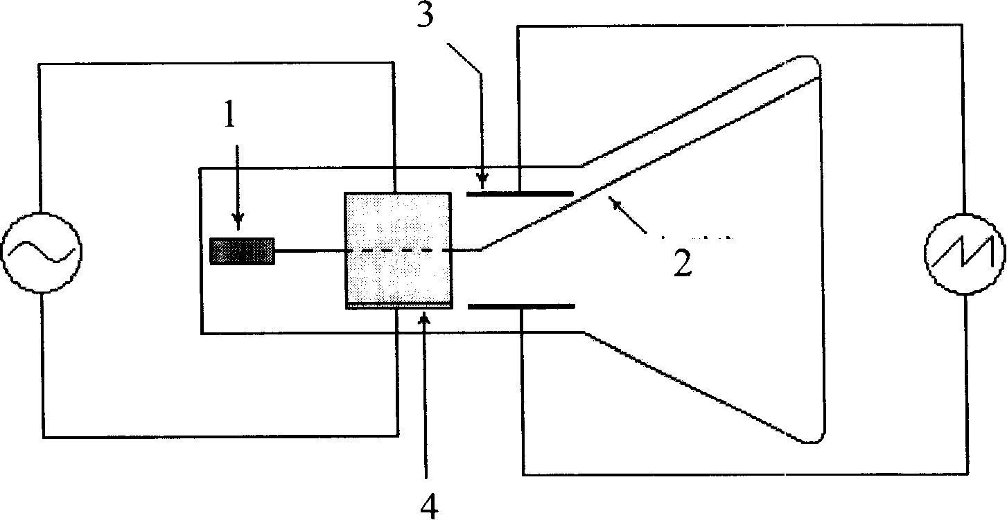
[0025] figure 1 It is the working principle of the electrical deflection circuit in the CRT display device. As shown in the figure, two pairs of orthogonal electric deflection plates 3 and 4 are shown in the figure. After the electron beam 2 is emitted from the cathode 1 , it is deflected in the Y direction under the action of the electric field between the Y-direction electric deflection plates 3 , and is deflected in the X-direction under the action of the electric field between the X-direction electric deflection plates 4 . The advantage of electric deflection is that the scanning linearity is good, the scanning frequency is high, and the scanning frequency or deflection rate can be changed arbitrarily. The disadvantage is that the deflection sensitivity is low and a high deflection voltage is required. Electrical deflection is generally used in small CRT display devices such as CRT oscilloscopes.

[0026] figure 2 It is a working diagram of the magnetic deflection circ...


PUM


Abstract

The invention relates to a CRT display device and a cathode ray tube. The CRT display device includes a cathode ray tube with an electron gun and the cathode ray tube includes a cathode, electrodes used for leading the electrons and accelerated electrons out from the cathode, a screen and a deflection circuit arranged between the cathode and the screen and used for deflecting the electron beam arranged in order; the deflection circuit is the combination of an electric deflection circuit and a magnetic deflection circuit and the electric deflection circuit comprises at least one pair of the electric deflecting plates; the magnetic deflection circuit comprises at least one pair of the magnetic deflection coils. By applying the electric deflection circuit in the large-size CRT display device and driving the electric deflection circuit and the magnetic deflection circuit together to be used as the deflection circuit of the electron beam, the invention effectively increases the deflection angle of the electron beam and leads to less thickness and larger screen area of the CRT display device.

Description

technical field [0001] The invention relates to CRT (cathode ray tube) image scanning and image display technology, in particular to a CRT display device and a cathode ray tube used therein. Background technique [0002] Common CRT display devices such as CRT oscilloscopes, CRT televisions and CRT computer monitors all have a deflection circuit for deflecting electron beams. There are currently two deflection scanning circuits, one is electric field deflection, referred to as electric deflection, and the other is magnetic field deflection, referred to as magnetic deflection. [0003] The principle of electric deflection is to install a pair or two pairs of plates in the display, and then apply a voltage to the two plates to generate an electric field between the plates. When the electron beam passes through the electric field, the electrons The beam will be deflected by the action of the electric field. The principle of electric deflection is as follows: figure 1 shown. ...

Claims


Application Information

Patent Timeline
Patent Type & Authority Applications(China)
IPC IPC(8): H01J29/70
Inventor 陶显芳
Owner KONKA GROUP
Why Eureka
Try Eureka