Air drying equipment for plastic extruded strips

A technology of plastics and strips, applied in the field of plastic granule production equipment, can solve the problems of increased production costs, poor air-drying effect, and wind direction control that cannot be air-dried, and achieve the effects of increasing air temperature, improving air-drying efficiency, and reducing adverse effects

Inactive Publication Date: 2018-07-06
王诗韵
View PDF1 Cites 4 Cited by
  • Summary
  • Abstract
  • Description
  • Claims
  • Application Information

AI Technical Summary

Problems solved by technology

However, the current existing technology has the problem of poor air-drying effect. Most of the air outlets of conventional air-drying equipment are set on the lower side of the plastic strips, so that the air-drying effect is not good, and if the number of plastic strips is too large, multiple air-drying equipment needs to be configured. , while the air-drying equipment has a large layout space, covers a large area, and consumes a lot of energy, which increases the production cost
For example, the patent application publication number 201720080153.0 discloses an air-drying equipment for plastic extruded strips, but there are certain defects in the use of the above patents. First of all, due to the size and weight of the equipment itself, it is difficult to Mobile, can not meet the special production needs of users, and secondly, in the process of air-drying the plastic, the equipment cannot control the air-drying wind direction, which may lead to different air-drying effects in different parts of the material. Finally, in the whole air-drying process, it is mainly aimed at the outer side of the plastic. Air-drying, the inside of the plastic cannot be air-dried, and the cutting surface of the granular plastic will not be completely air-dried when it is produced and cut into granular plastics

Method used


Image

  • Air drying equipment for plastic extruded strips
  • Air drying equipment for plastic extruded strips
  • Air drying equipment for plastic extruded strips

Examples


Embodiment Construction

[0024] The following will clearly and completely describe the technical solutions in the embodiments of the present invention with reference to the accompanying drawings in the embodiments of the present invention. Obviously, the described embodiments are only some, not all, embodiments of the present invention. Based on the embodiments of the present invention, all other embodiments obtained by persons of ordinary skill in the art without making creative efforts belong to the protection scope of the present invention.

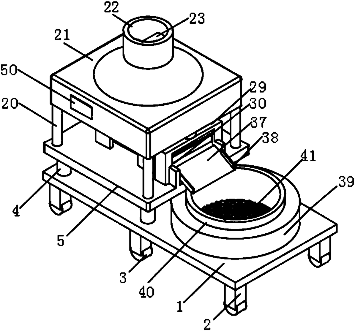
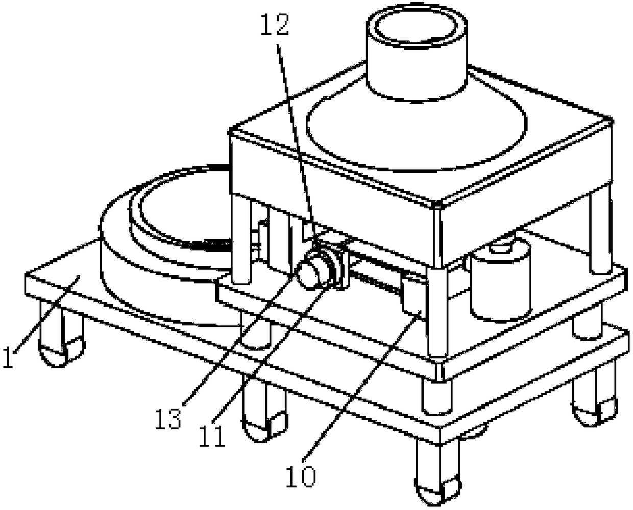
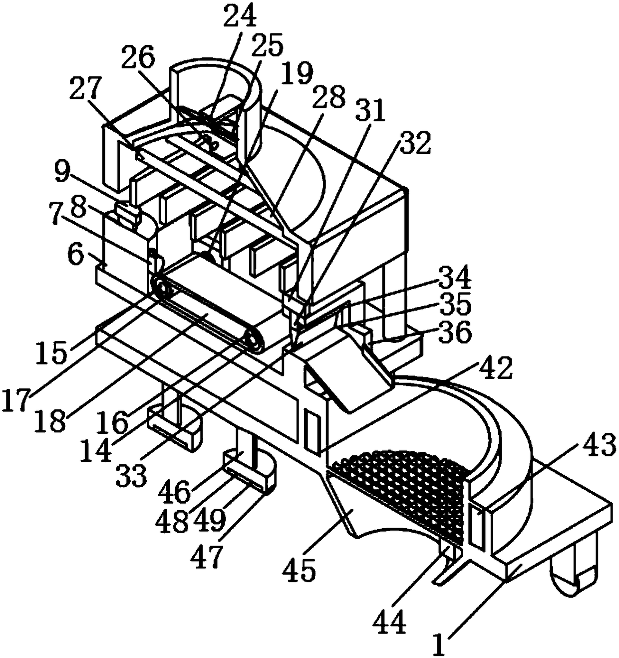
[0025] see Figure 1-3, the present invention provides a technical solution: an air-drying device for plastic extruded strips, comprising a bottom plate 1, the edge of the lower end surface of the bottom plate 1 is provided with legs 2, the number of legs 2 is not less than six, and the legs 2 are The edge of the lower end surface of the base plate 1 is evenly distributed, and four columns 4 are arranged on the left side of the upper end surface of the base pl...


PUM


Abstract

The invention discloses air drying equipment for plastic extruded strips. The air drying equipment comprises a bottom plate, wherein supporting feet are arranged on the edge of the lower end surface of the bottom plate; the number of the supporting feet is not smaller than 6; the supporting feet are uniformly distributed on the edge of the lower end surface of the bottom plate. According to the invention, through rollers, movement of the equipment can be achieved, so that a special production requirement of a user on the movement of the equipment in the production process can be met; meanwhile, through cooperative use of electric telescopic rods and counterweights, fixing of the equipment is achieved; furthermore, through vibration-proof gaskets on the bottom end surfaces of the counterweights, adverse effects of vibration generated by the equipment in the production process on other production processes are effectively reduced; through adjustment of rotating shafts 3, the inclinationangles of wind deflectors can be controlled so as to control the wind direction in the air drying process, and the air drying uniformity of plastic is guaranteed; moreover, air entering a main body isheated by heating tubes 1, so that the air drying efficiency of the plastic is greatly improved.

Description

technical field [0001] The invention relates to the technical field of plastic particle production equipment, in particular to an air-drying equipment for extruding plastic strips. Background technique [0002] Maleic anhydride, also known as maleic anhydride, is the anhydride of maleic acid. It is a colorless or white solid with a sour taste at room temperature. As a commonly used important basic organic chemical raw material, maleic anhydride is added as a plasticizer to plastic raw materials during the production of plastic granules to improve the flexibility of plastic products. However, maleic anhydride is volatile at high temperature so that it cannot be directly added to plastic raw materials during the production of plastic granules. So far, the usual method of using maleic anhydride as a toughening agent is to add maleic anhydride to a plastic resin in a super-normal amount to make a granular masterbatch, and only need to add the masterbatch when making plastic pro...

Claims


Application Information

Patent Timeline
Patent Type & Authority Applications(China)
IPC IPC(8): B29C47/08F26B21/00B26D1/06B29B9/06B29B9/16
CPCF26B21/001B26D1/06B29B9/06B29B9/16B29C48/0022B29C48/25B29B7/826B29B13/06
Inventor 王诗韵
Owner 王诗韵
Why Eureka
Try Eureka