Operation panel, elevator using the operation panel, and method of taking out intermediate panel of the operation panel

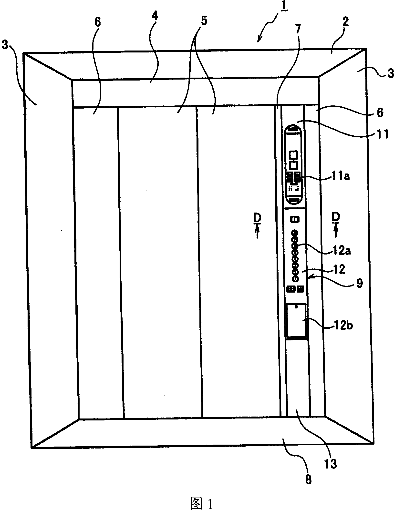
A technology for the middle panel and operation panel, which is applied in the direction of elevators, transportation and packaging, etc., and can solve problems such as difficulty in holding by hand, installation of the middle panel 12, setting gaps between the side panels 6 and the middle panel 12, etc.

Active Publication Date: 2008-07-09
TOSHIBA ELEVATOR KK
View PDF0 Cites 6 Cited by
  • Summary
  • Abstract
  • Description
  • Claims
  • Application Information

AI Technical Summary

Problems solved by technology

[0007] The bottom of the box body 10 is relatively shallow, and due to restrictions on the design, it is impossible to set a gap between the extension side plate 6 and the middle panel 12, so the middle panel 12 cannot be installed on the box body 10 by hinges.
[0008] Therefore, when the middle

Method used


Image

  • Operation panel, elevator using the operation panel, and method of taking out intermediate panel of the operation panel
  • Operation panel, elevator using the operation panel, and method of taking out intermediate panel of the operation panel
  • Operation panel, elevator using the operation panel, and method of taking out intermediate panel of the operation panel

Examples


no. 1 example

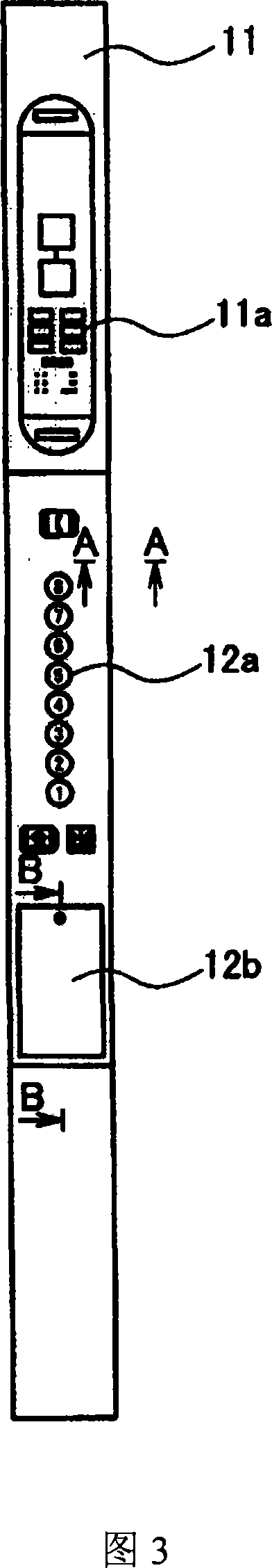
[0029] Fig. 3 is a front view of the operating panel in the car of the first embodiment of the present invention, Fig. 4A, Fig. 4B, Fig. 4C and Fig. 4D are perspective views of the operating panel in the car of Fig. 3, and Fig. 5 is the A-A line of Fig. 3 Sectional view, Fig. 6 is a view obtained from viewing the hinge unit from below, Fig. 7A, Fig. 7B, Fig. 7C and Fig. 7D are side sectional views of the first embodiment, Fig. 8 is a sectional view along line B-B of Fig. 3 , Fig. 9 is a view from below Transverse section view with the middle panel open.

[0030] In this embodiment, the same symbols are assigned to the same or similar parts as those of the above-mentioned conventional example, and repeated explanations are omitted.

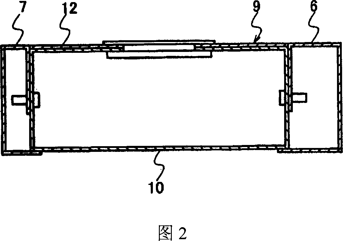
[0031] In FIG. 3 , the upper panel 11 is fixed to the box body 10 (see FIG. 4 ) with screws. As shown in Figure 4A, Figure 4B, Figure 4C and Figure 4D, a pair of upper and lower hinge units 14 are arranged in the box body 10, and these hinge units...

no. 2 example

[0042] Next, a second embodiment of the present invention will be described. Fig. 10 is a view of the hinge unit of the second embodiment seen from below. In each of the following embodiments, parts identical or similar to those of the first embodiment are assigned the same symbols, and repeated descriptions are omitted.

[0043] In this embodiment, the socket hinge 15 and the flat hinges 16 and 17 of the hinge unit 14 are integrated. In this way, compared with the case where the socket hinge 15 and the flat hinges 16, 17 are welded together as in the first embodiment, the thickness at the time of folding can be reduced, so that the operation panel can be further thinned.

no. 3 example

[0045] A third embodiment of the present invention will be described below. 11A, 11B, 11C and 11D are side cross-sectional views of the third embodiment.

[0046] In this embodiment, the lower end of the rod 23 is pivotally connected to the box body 10 through a pin 22 extending transversely (orthogonal to the paper plane of FIG. 11 ). In addition, the connecting member 25 is pivotally connected to the upper end of the rod 23 through a pin 24 extending laterally, and the support shaft 25 a protrudes vertically upward from the upper end of the connecting member 25 .

[0047] The bearing 26 is mounted on the upper part of one side of the back of the middle panel 12, and the bearing 26 has a top wall 26a protruding rearward from the upper end. A through hole is formed in the top wall 26a, and the support shaft 25a is rotatably penetrated through the through hole.

[0048] During maintenance and overhaul, the screws 21 for fixing the middle panel 12 are removed from the state sh...


PUM


Abstract

In the elevator operating panel of the present invention, the housing (10) is arranged approximately vertically. An upper panel (11), a middle panel (12) and a lower panel (13) are arranged approximately vertically at predetermined positions on the front surface of the box. A hinge unit (14) is arranged inside the box body (10) to support the middle panel (12). The hinge unit rotates forward centering on one side edge after advancing the middle panel (12).

Description

technical field [0001] The present invention relates to an operation panel, an elevator using the operation panel, and a method for taking out a middle panel of the operation panel. Background technique [0002] Fig. 1 is a front view of an elevator car viewed from the inside, and Fig. 2 is a sectional view taken along line D-D of Fig. 1 . [0003] As shown in Fig. 1 , the car 1 has a top plate 2, a side plate 3, a curtain plate 4, a door 5, a transfer side plate 6, an entrance column 7, a bottom plate 8 and an operating panel 9 in the car. [0004] As shown in FIG. 2 , a box 10 arranged substantially vertically is provided on the back surface of the operating panel 9 in the car. The box body 10 extends elongately in the vertical direction, and is fixed to the extension side plate 6 and the entrance column 7 by screws. [0005] The operating panel 9 in the car has a panel arranged approximately vertically at a predetermined position on the front sur...

Claims


Application Information

Patent Timeline
IPC IPC(8): B66B1/46
CPCB66B1/466
Inventor 池田恭一
Owner TOSHIBA ELEVATOR KK
Why Eureka
Try Eureka