Door checker for automobile

A technology for limiters and doors, which is applied to doors, manufacturing tools, vehicle parts, etc., can solve the problems of increased parts, high cost, and unsmooth operation of door switches, and achieves good elastic deformation characteristics and improves reliability.

Inactive Publication Date: 2008-07-16
HONDA MOTOR CO LTD
View PDF1 Cites 2 Cited by
  • Summary
  • Abstract
  • Description
  • Claims
  • Application Information

AI Technical Summary

Problems solved by technology

[0004] In conventional door stoppers for automobiles, since a space allowing elastic deformation of the elastic member is provided between the outer surface of the elastic member and the inner surface of the housing, rainwater may infiltrate into the space along the restricting plate or the like, and Once the rainwater freezes, the elastic deformation characteristics of the elastic parts will change, which will cause the unsmooth operation of the door switch
[0005] Therefore, there is also a method of covering the casing and the limiting plate with a waterproof cover to prevent rainwater from penetrating into the casing, but even with this structure, the casing cannot be completely waterproofed, and the number of parts increases, resulting in high cost.

Method used


Image

  • Door checker for automobile
  • Door checker for automobile
  • Door checker for automobile

Examples


Embodiment 1

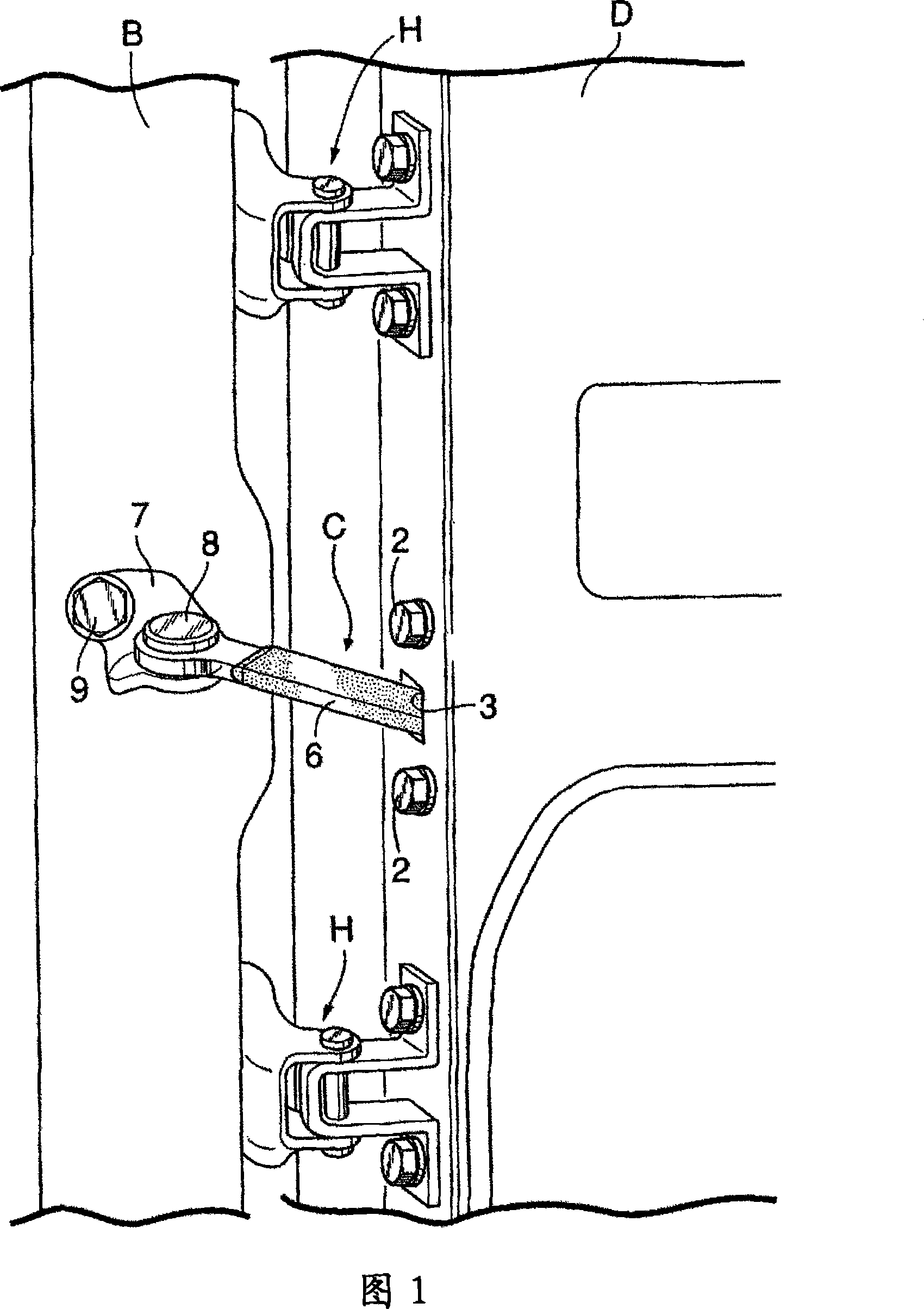
[0046] First, in FIG. 1 , on the body B of the automobile, a door D for opening and closing the landing is rotatably installed through a hinge H, and a door stopper of the present invention is installed between the body B and the door D. c.

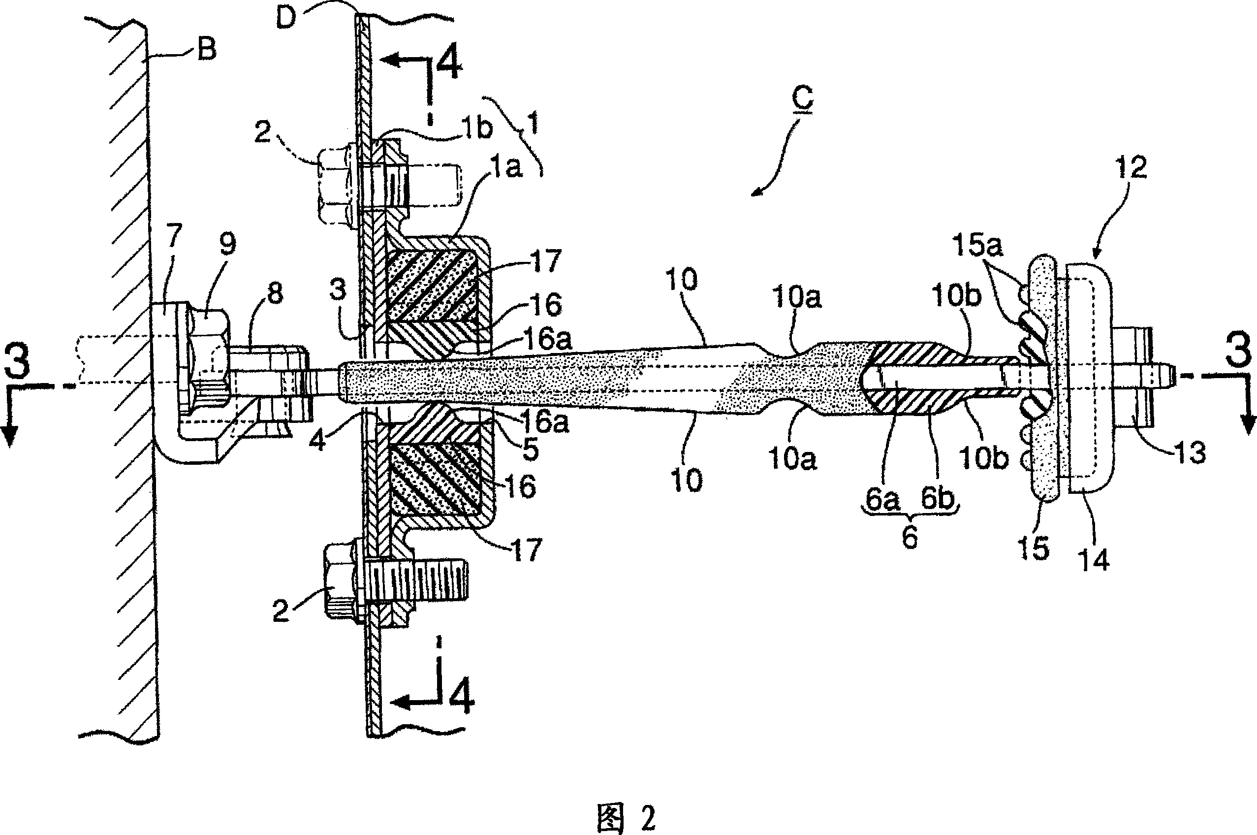
[0047] As shown in FIGS. 1 to 4 , the above-mentioned door stopper C has a housing 1 fastened to the inner surface of the end wall of the door D. As shown in FIG. The housing 1 includes: a box-shaped housing main body 1a with one end open; a cover 1b that covers the open end of the housing main body 1a and is coupled to the housing main body 1a by riveting parts 11, 11 (see FIG. 4 ), so that The cover 1b is abutted on the inner surface of the end wall of the door D, so that the housing main body 1a and the cover 1b are fastened to the end wall of the door D by a pair of upper and lower bolts 2,2. Through-holes 4, 5 are perforated on the cover 1b and the housing main body 1a. The through-holes 4, 5 are arranged coaxially with the through-...

Embodiment 2

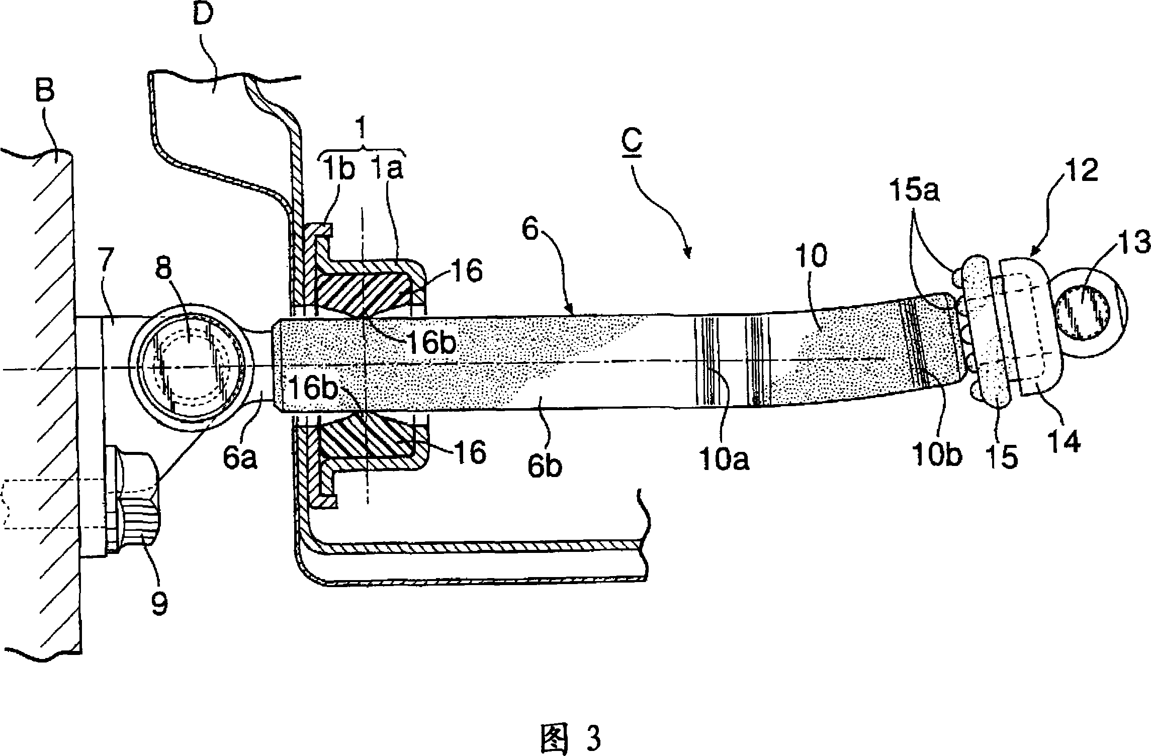
[0063] Next, a second embodiment of the present invention shown in FIG. 6 will be described.

[0064] This embodiment is the same as the previous embodiment except that the hard portion 17h of each elastic member 17 is provided with a concave portion 20 closed by the inner end surface 18b of the housing 1 or the outer end surface 18a of the stopper member 16. Therefore, the same reference numerals are assigned to the parts corresponding to those of the previous embodiment in FIG. 6, and repeated explanations are omitted.

[0065] According to this embodiment, the elastic deformation characteristic of the hard portion 17h of the elastic member 17 can be freely adjusted by the volume of the recessed portion 20 provided thereon. Moreover, since the recess 20 is closed by the inner end surface 18b of the housing 1 or the outer end surface 18a of the stopper member 16, it is possible to prevent rainwater from penetrating into the recess 20 in a simple manner, so that the elastic de...


PUM


Abstract

The invention provides a door restrictor for automobiles, comprising: a casing (1), which is fixed to the door (D); a restricting plate (6), whose base end is pivotally supported on the vehicle body (B), and Through the housing (1); the stop part (16), which is fitted and held in the housing (1), and cooperates with the stop surface (10) of the limiting plate (6); the elastic part made of elastic material (17), which is compressed and arranged in the accommodation chamber (18) formed between the outer end surface (18a) of the stopper (16) and the inner end surface (18b) of the housing (1), the elastic member (17 ) is substantially tightly packed in the accommodation chamber (18), so that rainwater cannot penetrate into the accommodation chamber (18). Therefore, it is possible to prevent rainwater from penetrating into the accommodation chamber of the case housing the elastic member with a simple structure.

Description

technical field [0001] The present invention relates to an improvement of a door stopper for an automobile. The door stopper for an automobile has: a casing fastened to a body of the automobile and one of a door rotatably pivoted to the body; The housing is movably penetrated and connected to the other of the vehicle body and the door; a stopper member is fitted and held in the housing in a slidable manner, and is connected to the stopper surface of the restricting plate. Working together to keep the door at a specified open position; an elastic member made of elastic material, which is compressed and arranged on the outer end surface of the above-mentioned stop member opposite to the above-mentioned limiting plate and the above-mentioned housing facing the outer end surface In the accommodating chamber formed between the inner end faces of the stopper, a stopping force is generated between the above-mentioned stopper member and the stopper surface. Background technique [...

Claims


Application Information

Patent Timeline
Patent Type & Authority Applications(China)
IPC IPC(8): E05C17/22B60J5/04
CPCE05B17/002E05C17/206
Inventor 田岛雄二郎伊集院英俊吉田康彦
Owner HONDA MOTOR CO LTD
Why Eureka
Try Eureka