
Aligning jump hammer tamping tool

A technology of tamping machine and splint hammer, which is applied in the mechanical treatment of coal loaded into the furnace, the petroleum industry, coking ovens, etc., and can solve the problems of difficult adjustment of manufacturing assembly, deviation wear, high cost, etc.

Active Publication Date: 2011-04-20
大连华宇冶金设备有限公司
View PDF0 Cites 0 Cited by
  • Summary
  • Abstract
  • Description
  • Claims
  • Application Information

AI Technical Summary

Problems solved by technology

However, such a pair of half-ring friction cams arranged on both sides of the tamping hammer rod for pressure compensation requires a set of swing transmission pair, and the mechanism is relatively complicated; a pair of half-ring friction cams must ensure parallel contact with both sides of the tamping hammer rod at the same time , it is difficult to adjust the manufacturing assembly, and it is easy to cause deviation and wear
In particular, a pair of half-ring friction cams and rotating devices arranged on both sides of the tamping hammer rod and this set of swing transmission pairs require relatively high precision during manufacture, so the cost is high, and the alignment must be determined at the same time during assembly. For the half-ring friction cam and a set of oscillating transmission pairs, the assembly and debugging are particularly time-consuming and troublesome
For multiple groups of tamping hammers, a pair of half-ring friction cams of each group share one input shaft, which increases the difficulty of adjusting the position of each group. At the same time, if a driving mechanism of a tamping hammer fails, the entire unit must be shut down. The tamping hammer of the

Method used


Image

  • Aligning jump hammer tamping tool
  • Aligning jump hammer tamping tool
  • Aligning jump hammer tamping tool

Examples


specific Embodiment

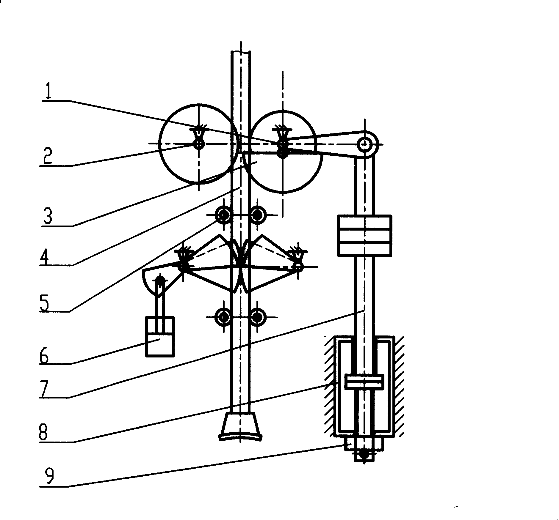
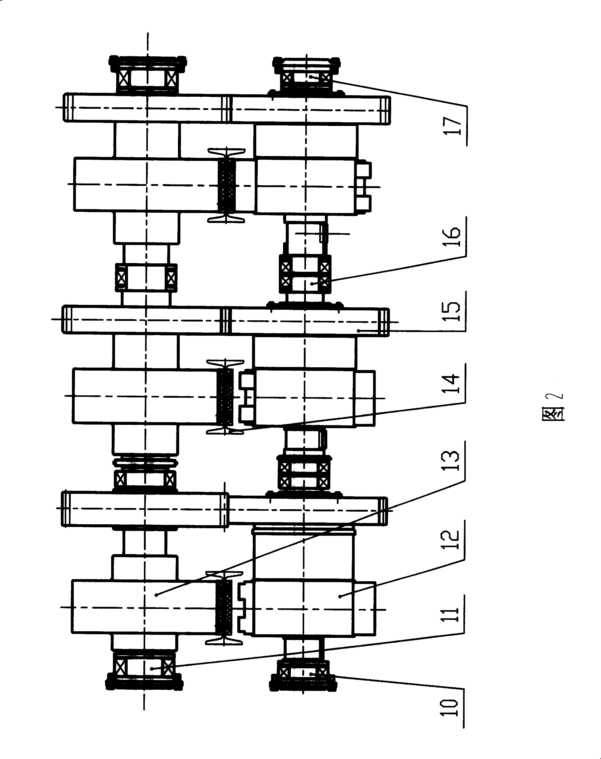
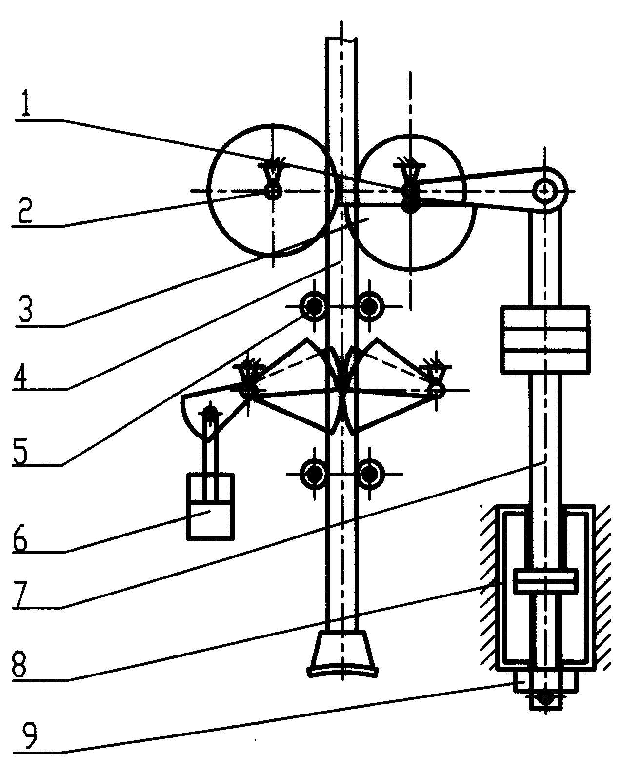
[0008] Specific embodiment: this self-aligning type splint hammer tamping machine as shown in the accompanying drawing has car body, the frame that is arranged on car body, the driving transmission mechanism that is arranged on frame and lifts the hammer mechanism, also is arranged on Tamping hammer 4 between frame guide wheel group 5. The car body also has a walking mechanism. The lower end of the frame is provided with an electric control mechanism and an operating mechanism. It is characterized in that the clamping parts of the hammer lifting mechanism are a friction wheel 2 and a half-ring friction cam 3 respectively arranged on both sides of the tamping hammer rod. The synchronously meshed gear 15 of the friction wheel and the half-ring friction cam meshes with the transmission gear of the drive transmission (see FIG. 2 ). The hammer lifting mechanism, the guide wheel group and the tamping hammer that are arranged on the frame are three groups (see Fig. 2) juxtaposed, a...


PUM


Abstract

The invention relates to an aligning tamping tool of friction-board hammer, comprising a vehicle body, a frame as well as a hammer lifting mechanism which is arranged on the frame and connected with a drive mechanism and a hammer which is arranged between the directive wheel sets. The clamp parts of the hammer lifting mechanism comprises a friction wheel and a semiring friction cam which are arranged on the two sides of the hammer respectively and provided with a gear meshed synchronous. The shafts of the friction wheel and the gear are movably matched with a bearing support and the semiring friction cam and the gear are movably matched with a swing part. The swing shaft of the swing part is movably matched with the bearing support and provided with a balance weight part. The balance weight part is only arranged on the swing part on one side, so the swing transmission pair is removed. The circular friction wheel is easy to machine, assemble and fix. The semicircular friction cam is easy to assemble and fix by taking the circular friction wheel as the benchmark. The balance weight part drives the swing part, which makes the pressure of the semiring friction cam forced on the hammerrod constant and enables to achieve automatic compensation.

Description

Technical field: [0001] The self-aligning splint hammer tamping machine is a tamping machine that tamps loose coal to form briquettes in the coking equipment that is filled with coal cakes sideways for coking. Background technique: [0002] The existing side-loaded coal coke oven tamping machine has a car body, a frame arranged on the car body, a driving transmission mechanism and a hammer lifting mechanism arranged on the car body or frame, and a set of guide wheels arranged on the frame. The tamping hammer between them, the clamping part of the said lifting hammer mechanism is a pair of semi-ring friction cams arranged on both sides of the tamping hammer rod, the coaxial gear of the half-ring friction cam and a pair of synchronous transmission of the drive transmission mechanism The gears are meshed separately, the shafts of a pair of swing transmission pairs are respectively coaxial with the corresponding large synchronous transmission gears, the outer drive end of the sw...

Claims


Application Information

Patent Timeline
Patent Type & Authority Patents(China)
IPC IPC(8): C10B37/04
Inventor 安邦田
Owner 大连华宇冶金设备有限公司
Learn More