
Sighting system and unmanned aerial vehicle

An unmanned aerial vehicle (UAV) and scope technology, applied in the field of aviation aircraft, can solve the problems of inconvenience of use, limitation of the UAV aiming range and aiming distance, and inability to increase the zoom magnification of infrared thermal imaging equipment, so as to increase the aiming range and The effect of aiming distance and ensuring aiming accuracy

Pending Publication Date: 2019-09-20
SHENYANG WOOZOOM TECH CO LTD
View PDF0 Cites 0 Cited by
  • Summary
  • Abstract
  • Description
  • Claims
  • Application Information

AI Technical Summary

Problems solved by technology

[0003] At present, UAVs usually aim and locate through the infrared thermal imaging equipment installed on the fuselage. Specifically, the aiming range is controlled by the zoom magnification of the infrared thermal imaging equipment. As a result, the zoom magnification of the infrared thermal imaging device on the fuselage cannot be increased, resulting in the limitation of the aiming range and aiming distance of the drone, which is inconvenient to use

Method used


Image

  • Sighting system and unmanned aerial vehicle
  • Sighting system and unmanned aerial vehicle

Examples


Embodiment Construction

[0031] In order to make the purpose, technical solutions and advantages of the present invention clearer, the technical solutions in the embodiments of the present invention will be described in more detail below with reference to the drawings in the preferred embodiments of the present invention. In the drawings, the same or similar reference numerals denote the same or similar elements or elements having the same or similar functions throughout. The described embodiments are some, but not all, embodiments of the invention. The embodiments described below by referring to the figures are exemplary and are intended to explain the present invention and should not be construed as limiting the present invention. Based on the embodiments of the present invention, all other embodiments obtained by persons of ordinary skill in the art without creative efforts fall within the protection scope of the present invention. Embodiments of the present invention will be described in detail b...


PUM


Abstract

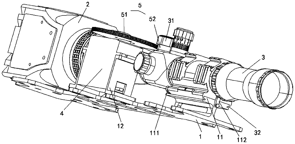
The invention discloses a sighting system and an unmanned aerial vehicle, and relates to the technical field of aviation aircrafts. The sighting system mainly aim to improve the sighting range and the sighting distance of the unmanned aerial vehicle, so that the use convenience of the unmanned aerial vehicle is improved. According to the main technical scheme, the sighting system comprises a base, imaging equipment, a sighting telescope and a driving part, wherein the base is used for being connected to a machine body of the unmanned aerial vehicle; the imaging equipment is arranged on the base and is used for being electrically connected to a flight control system of the unmanned aerial vehicle; the sighting telescope is arranged on the base, an eyepiece end of the sighting telescope is opposite to a camera of the imaging equipment, an optical axis of the sighting telescope coincides with an optical axis of the camera, and the sighting telescope is provided with a rotary knob for adjusting the magnification; and the driving part is arranged on the base and is used for being electrically connected to the flying control system of the unmanned aerial vehicle, and the driving part is connected to the rotary knob through a transmission mechanism and is used for driving the rotary knob to rotate. The sighting system is mainly used for improving the sighting range and the sighting distance of the unmanned aerial vehicle.

Description

technical field [0001] The invention relates to the technical field of aviation aircraft, in particular to an aiming system and an unmanned aerial vehicle. Background technique [0002] The application and development of UAVs in various industries is becoming more and more extensive. At this stage, UAVs have been applied to aerial photography, agricultural and forestry plant protection, geological exploration, power inspection, oil and gas pipeline inspection, highway accident management, forest fire prevention inspection and environmental pollution. Surveying and other fields. [0003] At present, UAVs usually aim and locate through the infrared thermal imaging equipment installed on the fuselage. Specifically, the aiming range is controlled by the zoom magnification of the infrared thermal imaging equipment. As a result, the zoom magnification of the infrared thermal imaging device on the fuselage cannot be increased, resulting in the limitation of the aiming range and ai...

Claims


Application Information

Patent Timeline
IPC IPC(8): B64D47/00B64C27/52H04N5/232
CPCB64D47/00B64C27/52H04N23/67
Inventor 张震肖川
Owner SHENYANG WOOZOOM TECH CO LTD
Learn More