
Method for calibrating optical axis and pupil of light beam tracking and pointing equipment

An optical axis and pupil technology, applied in the field of photoelectric tracking and aiming imaging, can solve the problems of large detection system space, high cost, real-time equipment aiming accuracy, poor stability, etc., achieve high beam reduction ratio, long focal length, and ensure tracking Effect of Accuracy and Aiming Accuracy

Active Publication Date: 2022-01-21
AEROSPACE SCI & IND MICROELECTRONICS SYST INST CO LTD
View PDF5 Cites 2 Cited by
  • Summary
  • Abstract
  • Description
  • Claims
  • Application Information

AI Technical Summary

Problems solved by technology

[0003] At present, the existing technology has the following disadvantages: due to the deviation of the optical axis of the main laser emission, the visual axis of the imaging optics, and the mechanical axis of the photoelectric turntable, the tracking accuracy and aiming accuracy of the system need to be improved; at the same time, the imaging band and the laser emission band are not The same band results in the need for two detection systems, which require a large space and high cost
At the same time, the optical axis of the product changes due to complex environments such as temperature and vibration, resulting in poor real-time performance and stability of equipment aiming accuracy

Method used


Image

  • Method for calibrating optical axis and pupil of light beam tracking and pointing equipment
  • Method for calibrating optical axis and pupil of light beam tracking and pointing equipment
  • Method for calibrating optical axis and pupil of light beam tracking and pointing equipment

Examples


Embodiment Construction

[0037] All features disclosed in all embodiments in this specification, or steps in all implicitly disclosed methods or processes, except for mutually exclusive features and / or steps, can be combined and / or extended and replaced in any way.

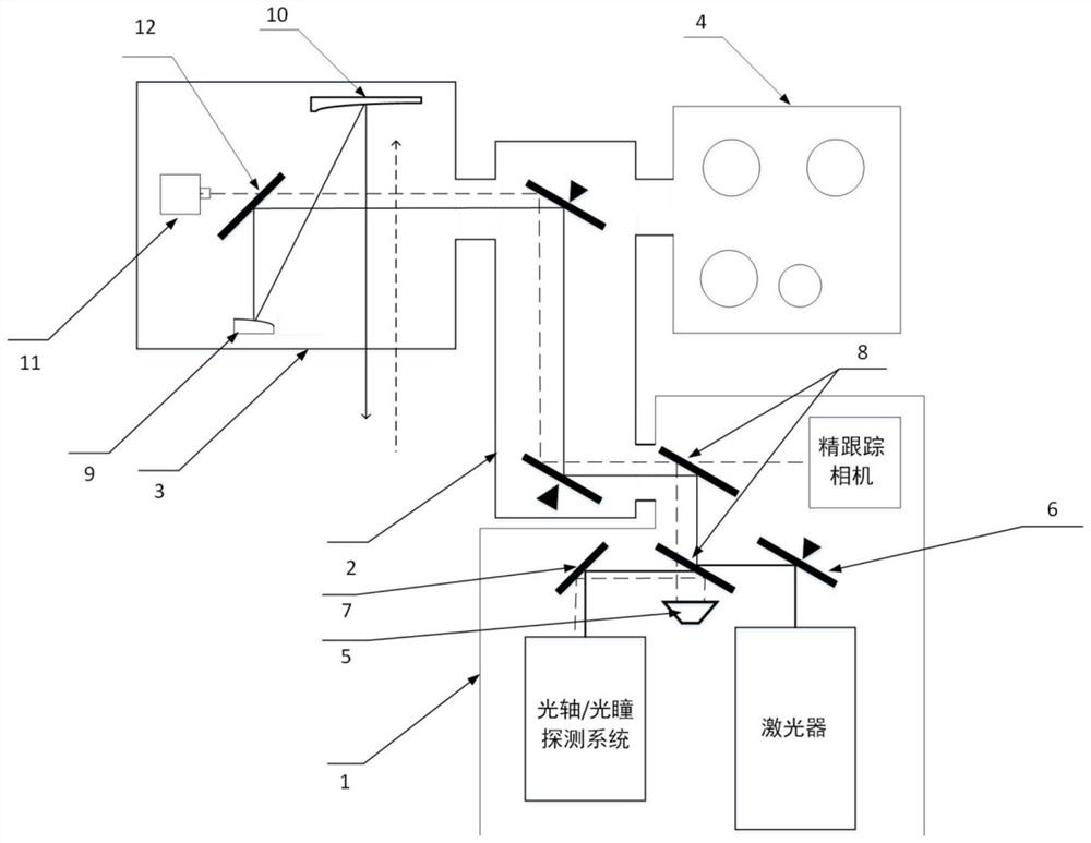
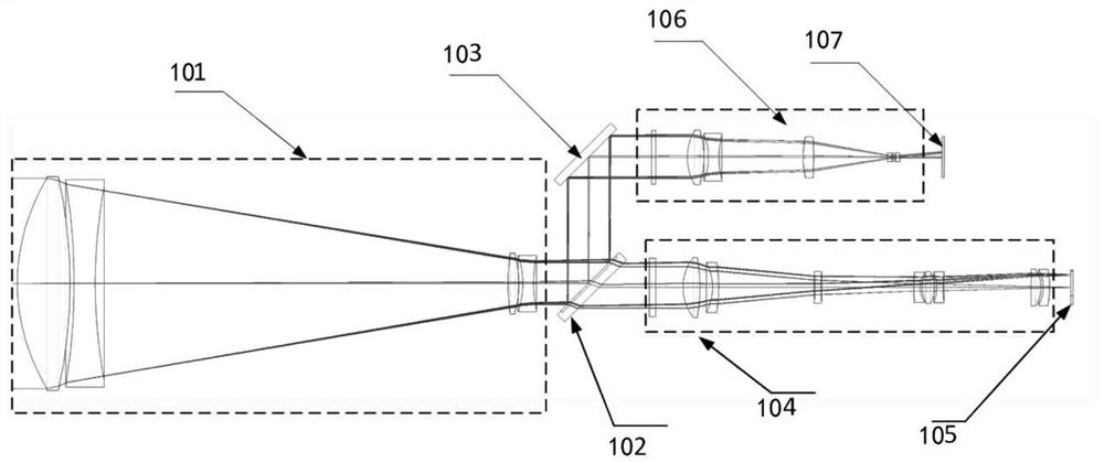
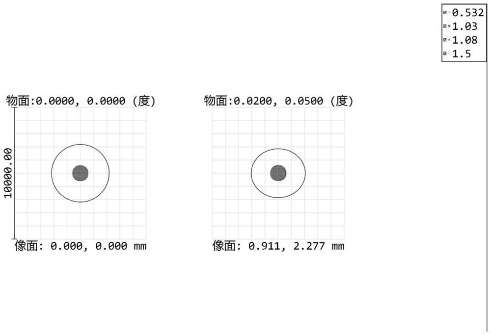
[0038] Such as Figure 1 to Figure 6 As shown, a method for optical axis pupil calibration of beam tracking equipment includes the steps of: imaging on the optical axis and pupil camera with reference light, making differences with the calibrated position and angle after imaging, and then controlling the adjustment The attitude of the fast mirror realizes the calibration of the imaging optical axis, the emitting optical axis and the mechanical axis of the turntable.

[0039] In an optional embodiment, substeps are included:

[0040] S1, control the rotation of the photoelectric turntable of the beam tracking equipment, and calibrate the optical axis and the mechanical axis of the photoelectric turntable;

[0041] S2, through the rotatio...


PUM


Abstract

The invention discloses a method for calibrating an optical axis and a pupil of light beam tracking and pointing equipment. The comprises the following steps of: imaging on an optical axis and pupil camera through reference light, subtracting from a calibrated position and a calibrated angle after imaging, and then controlling and adjusting the attitude of a fast reflecting mirror to realize calibration of an imaging optical axis, a transmitting optical axis and a rotary table mechanical axis. According to the method, dynamic coincidence of the imaging optical axis, the transmitting optical axis and the mechanical axis is realized, optical axis changes, caused by complex environments such as temperature and vibration, of a product is eliminated, the aiming precision of the equipment is improved, and the method has the advantages that real-time performance, stability and a dynamic closed loop are achieved.

Description

technical field [0001] The present invention relates to the technical field of photoelectric tracking and aiming imaging, and more specifically, to a method for calibrating the optical axis and pupil of beam tracking and aiming equipment. Background technique [0002] Beam control and tracking and aiming equipment (ATP for short) is an important part of laser directed energy weapons. Its purpose is to transfer high-energy laser to the transmitting telescope through the photoelectric tracking and aiming platform, focus the laser on the far-field target, and achieve strike and attack on the target. destroy. The main function is to complete the functions of target tracking and detection, optical axis calibration of the inner optical path, and high-precision aiming. [0003] At present, the existing technology has the following disadvantages: due to the deviation of the optical axis of the main laser emission, the visual axis of the imaging optics, and the mechanical axis of th...

Claims


Application Information

Patent Timeline
Patent Type & Authority Applications(China)
IPC IPC(8): F41G1/16G02B7/00G02B7/182F41H13/00
CPCF41G1/16G02B7/005G02B7/1821F41H13/005
Inventor 武春风王晓丹吴丰阳董理治江颖马社
Owner AEROSPACE SCI & IND MICROELECTRONICS SYST INST CO LTD
Learn More