Light path system for photoelectric tracking active tomography illumination

A technology of photoelectric tracking and optical path system, which is applied in the direction of radio wave measurement system, optics, optical components, etc., can solve the problems that cannot meet the tracking accuracy of photoelectric tracking and aiming equipment, is difficult to adapt to complex environmental conditions, and has high requirements for the working environment. Reduce stray light interference, easy to implement, and suppress the effect of stray light interference

Active Publication Date: 2021-04-02
AEROSPACE SCI & IND MICROELECTRONICS SYST INST CO LTD
View PDF27 Cites 6 Cited by
  • Summary
  • Abstract
  • Description
  • Claims
  • Application Information

AI Technical Summary

Problems solved by technology

[0003] Based on a variety of combat application environments, in order to achieve all-weather detection, identification and tracking of targets, especially for tracking targets at night, the frame rate of existing infrared detectors cannot meet the tracking accuracy of photoelectric tracking and aiming equipment, and visible light cameras cannot be seen at night.
Throu

Method used


Image

  • Light path system for photoelectric tracking active tomography illumination
  • Light path system for photoelectric tracking active tomography illumination
  • Light path system for photoelectric tracking active tomography illumination

Examples


Embodiment Construction

[0026] All features disclosed in all embodiments in this specification (including any appended claims, abstract and drawings), or steps in all methods or processes implicitly disclosed, except for mutually exclusive features and / or steps, can be used as Combining and / or extending, replacing in any way.

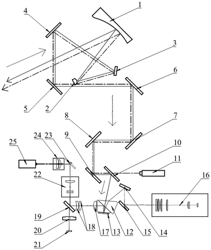
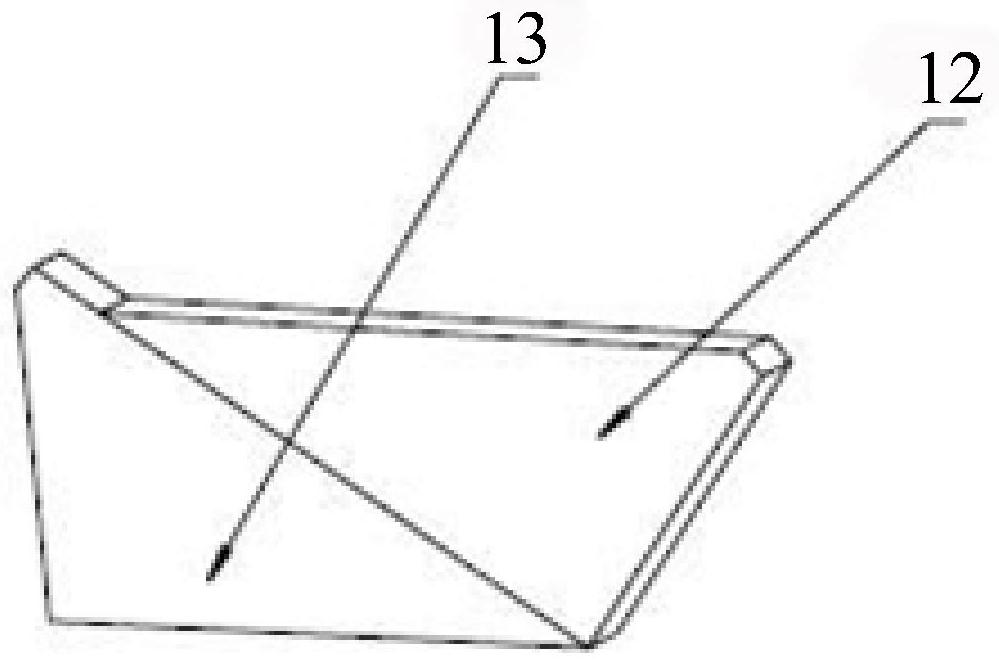
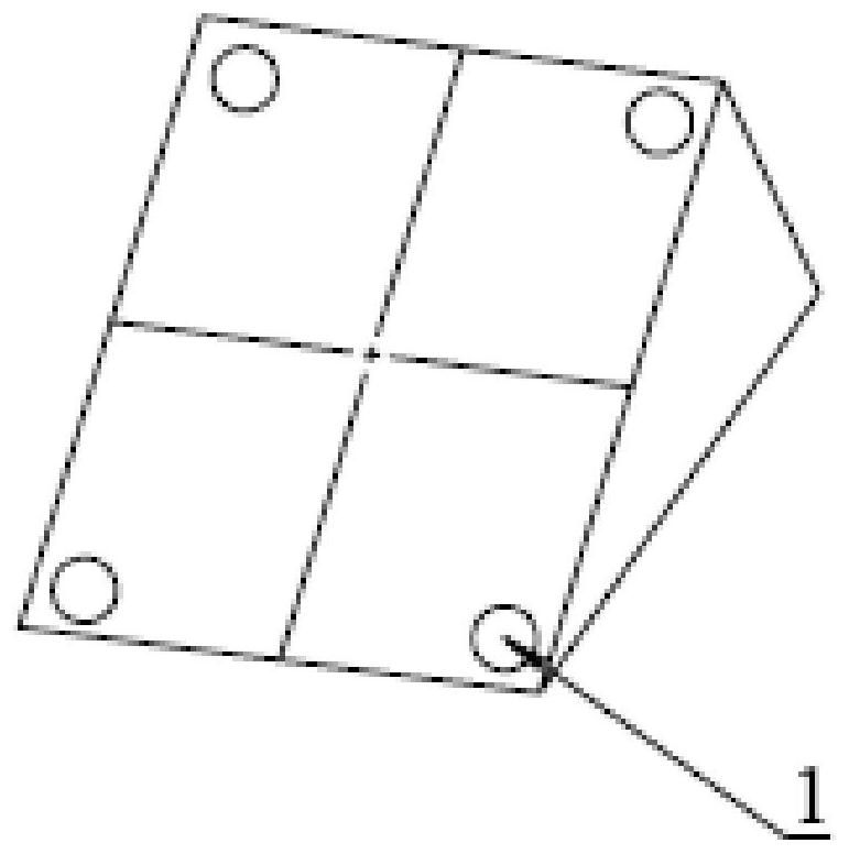
[0027] like Figure 1-7 As shown, the optical path system for photoelectric tracking active tomographic illumination includes a transmitting telescope, a fast mirror 3, multiple Coud mirrors, a beam splitter 10, a transmitting laser 11, an illumination pulse laser 25, a short-wave optical imaging system 16, TIR Prism, relay DLP chip imaging optical system, illumination laser optical axis calibration optical system, illumination laser beam shrinkage system 22, illumination laser collimation lens 24, described multiple Coud mirrors form Coud optical path; illumination pulse laser 25 sends After the laser passes through the TIR prism, it enters the DLP chip unit of the DLP chip ...


PUM


Abstract

The invention discloses a light path system for photoelectric tracking active tomography illumination. The system comprises a transmitting telescope, a fast reflecting mirror, a plurality of Coude mirrors, a spectroscope, a transmitting laser, an illumination pulse laser, a short-wave optical imaging system, a TIR prism, a relay DLP chip imaging optical system, an illumination laser optical axis calibration optical system, an illumination laser beam shrinking system, an illumination laser collimating lens, a Coude optical path formed by the plurality of Coude mirrors and the like. The system has the advantages of being capable of detecting and imaging an ultra-long-distance target around the clock, reducing stray light interference, achieving detection and imaging of the target in a complex environment, reducing the size of the photoelectric tracking and pointing device and the like.

Description

technical field [0001] The invention relates to the technical field of laser active lighting in photoelectric tracking and aiming equipment, and more specifically, to an optical path system for photoelectric tracking active tomographic lighting. Background technique [0002] Beam Control and Tracking and Targeting Equipment (ATP for short) is an important part of laser weapons and multi-functional laser combat vehicles. Achieve strike and destroy. The main function is to complete the functional links such as high-power laser transmission, pointing control, target recognition and tracking, active lighting, aiming and striking. [0003] Based on a variety of combat application environments, in order to achieve all-weather detection, identification and tracking of targets, especially for tracking targets at night, the frame rate of existing infrared detectors cannot meet the tracking accuracy of photoelectric tracking and aiming equipment, and visible light cameras cannot be s...

Claims


Application Information

Patent Timeline
IPC IPC(8): G02B23/06G02B23/02G02B23/12G01S7/481
CPCG02B23/06G02B23/02G02B23/12G01S7/481
Inventor 武春风王晓丹吴丰阳高洋朱珺梁国斌
Owner AEROSPACE SCI & IND MICROELECTRONICS SYST INST CO LTD
Why Eureka
Try Eureka