

A camera switching module and its manufacturing method
A technology for switching modules and manufacturing methods, which is applied in the direction of optical filters, optics, and instruments for photography, and can solve problems such as mutual interference and affecting the effect of day and night switching of cameras, so as to reduce stray light, improve the effect of day and night switching, and reduce The effect of stray light interference
- Summary
- Abstract
- Description
- Claims
- Application Information
AI Technical Summary
Problems solved by technology
Method used
Image

Examples
Embodiment 1
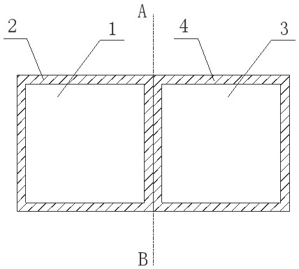
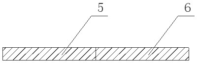
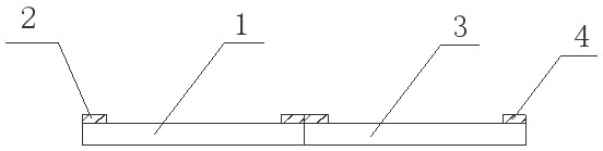
[0036] A camera switching module, such as Figure 1~3As shown, it includes an infrared cut filter 1 and a full-spectrum optical glass 3 installed side by side. The infrared cut-off filter 1 and the full-spectrum optical glass 3 are distributed on both sides of the separation line AB, and the light-shielding layers arranged on both sides of the separation line AB separate the infrared cut-off filter 1 and the full-spectrum optical glass 3 to form independent transparent The light area reduces the stray light interference between each other and improves the day and night switching effect of the camera. The thickness of the light-shielding layer is 0.2-0.5mm.
[0037] In this embodiment, the upper surface of the infrared cut-off filter is provided with a "return" shaped light-shielding layer 2 along the edge of the surface to define and form a light-transmitting area. The "back" shape shading layer 4 in the area, the infrared cut-off filter and the full-spectrum optical glass i...
Embodiment 2
[0040] A camera switching module, such as Figure 4~6 As shown, it includes an infrared cut filter 1 and a full-spectrum optical glass 3 installed side by side. The infrared cut-off filter 1 and the full-spectrum optical glass 3 are distributed on both sides of the separation line AB, and the light-shielding layers arranged on both sides of the separation line AB separate the infrared cut-off filter 1 and the full-spectrum optical glass 3 to form independent transparent The light area reduces the stray light interference between each other and improves the day and night switching effect of the camera. The thickness of the light-shielding layer is 0.2-0.5mm.
[0041] In this embodiment, the upper surface of the infrared cut-off filter is provided with an "inverted L"-shaped light-shielding layer 2 along the edge of the surface, defining and forming a light-transmitting area, and the upper surface of the full-spectrum optical glass is provided with an The "L"-shaped light-shie...
Embodiment 3
[0044] A camera switching module, such as Figure 7~9 As shown, it includes an infrared cut filter 1 and a full-spectrum optical glass 3 installed side by side. The infrared cut-off filter 1 and the full-spectrum optical glass 3 are distributed on both sides of the separation line AB, and the light-shielding layers 2 and 4 arranged on both sides of the separation line AB make the infrared cut-off filter 1 and the full-spectrum optical glass 3 separately formed The independent light-transmitting area reduces the interference of stray light and improves the day-night switching effect of the camera. The thickness of the light-shielding layer is 0.2-0.5mm. In this embodiment, there is no annular light-shielding layer and side light-shielding layers.
[0045] The manufacturing method of the above-mentioned camera switching module includes the following process: install the infrared cut filter and the full-spectrum optical glass side by side on both sides of a separation line, for...
PUM
| Property | Measurement | Unit |
|---|---|---|
| thickness | aaaaa | aaaaa |
Abstract
Description
Claims
Application Information