
Conduction-type polarizing and beam-splitting synchronized lighting device

A polarization splitting and lighting device technology, which is applied in projection devices, light guides, optics, etc., can solve the problems of increasing the volume and moment of inertia of the rotating optical path, the large loss of light energy in the synchronous lighting optical path, and the large aperture of the optical element, so as to achieve uniform lighting source The effect of modernization, simple structure and convenient installation

Active Publication Date: 2015-03-18
BEIJING INSTITUTE OF TECHNOLOGYGY +1
View PDF4 Cites 0 Cited by
  • Summary
  • Abstract
  • Description
  • Claims
  • Application Information

AI Technical Summary

Problems solved by technology

Wherein there are following problems, first, the illumination light that adopts is natural light, because the commonly used LCD and LCOS spatial light modulator require linearly polarized light illumination at present, so the light energy loss of synchronous illumination light path is bigger; One-to-one setting, the quantity is large, and the cost is high; in addition, the distance between the incident end of the beam transmission or the aperture and the rotating shaft is relatively long, generally between 300 and 800mm, and the projection distance of the illumination source is correspondingly relatively long. It is also correspondingly larger, thereby increasing the volume and moment of inertia of the rotating optical path

Method used


Image

  • Conduction-type polarizing and beam-splitting synchronized lighting device
  • Conduction-type polarizing and beam-splitting synchronized lighting device
  • Conduction-type polarizing and beam-splitting synchronized lighting device

Examples


Embodiment Construction

[0019] In the following, preferred embodiments according to the present invention will be described in detail with reference to the accompanying drawings. For the convenience of describing and highlighting the present invention, relevant components existing in the prior art are omitted from the drawings, and the description of these known components will be omitted.

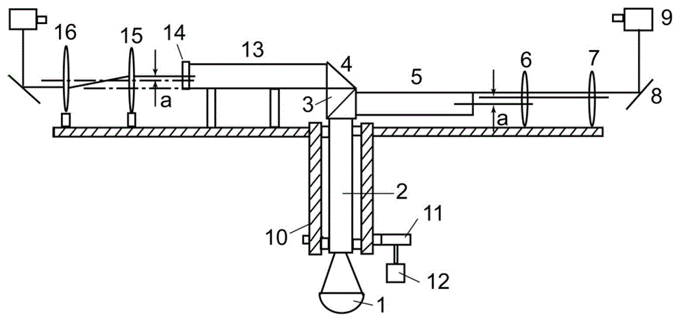
[0020] figure 1 Shown is the optical path of the transmitted polarized light synchronous illuminator. The light source 1 is a reflective cup-type lighting source, and other types of lighting sources can also be used. The light emitted by the light source is focused on the light guide rod 2. The cross-sectional shape of the light guide rod can be circular, square, or rectangular, or a circle can also be used. A light guide rod with a rectangular incident end and a square or rectangular output end, and the exit end surface of the light guide rod is in close contact with or bonded to the polarization beam splitter ...


PUM


Abstract

The invention provides a conduction-type polarizing and beam-splitting synchronized lighting device. The lighting device comprises a light source, a light guide stick, a polarizing and beam-splitting prism, a first lens, a polarized light conversion unit and a second lens, wherein light emitted by the light source is focused on the light guide stick; the incident face of the polarizing and beam-splitting prism is bonded with the exit face of the light guide stick; the polarizing and beam-splitting prism divides incident light into a first linearly polarized light and a second linearly polarized light; the first lens projects the first linearly polarized light to one of a plurality of first projectors; the polarized light conversion unit converts the polarization direction of the second linearly polarized light to be the same as that of the first linearly polarized light; and the second lens projects the second linearly polarized light of which the polarization direction is converted to one of a plurality of second projectors. The lighting device adopts the polarizing and beam-splitting prism to divide natural light of the light source into two paths of linearly polarized light, converts natural light into linearly polarized light while achieving beam-splitting, improves the light efficiency and lowers interference of parasitic light in the projectors.

Description

technical field [0001] The present application relates to an illuminating device, in particular to a conductive polarization splitting synchronous illuminating device used in a projector. Background technique [0002] The projectors of the multi-projector true three-dimensional display are arranged in a circle. When the flat screen turns to face the projector, the projector projects the graphics of the corresponding cross-section. The screen rotates continuously, and the persistence of human vision will pass through the series of cross-sectional images of the rotating shaft. Synthesize a complete true three-dimensional image. To reconstruct an undistorted true three-dimensional image, the screen rotation should be completely synchronized with the projector lighting. [0003] In the Chinese patent application CN101038421A, a multi-projector layout scheme and multiple illumination light paths are disclosed, in which at least two projectors are used, placed around a rotating sc...

Claims


Application Information

Patent Timeline
Patent Type & Authority Patents(China)
IPC IPC(8): G03B21/20G02B27/28G02B6/00
Inventor 朱秋东王涌天黄涛
Owner BEIJING INSTITUTE OF TECHNOLOGYGY
Learn More