Shearing type lead damper

A technology of shear type and damper, which is applied in the direction of building components, earthquake resistance, etc., to achieve the effect of simplified connection, high practical application value, and simple structure

Inactive Publication Date: 2008-07-23
BEIJING UNIV OF TECH
View PDF0 Cites 27 Cited by
  • Summary
  • Abstract
  • Description
  • Claims
  • Application Information

AI Technical Summary

Problems solved by technology

[0003] The purpose of the present invention is to solve the connection problem between the shearing lead column 6 and the

Method used


Image

  • Shearing type lead damper
  • Shearing type lead damper
  • Shearing type lead damper

Examples


Example Embodiment

[0013] The present invention will be further described below in conjunction with embodiments.

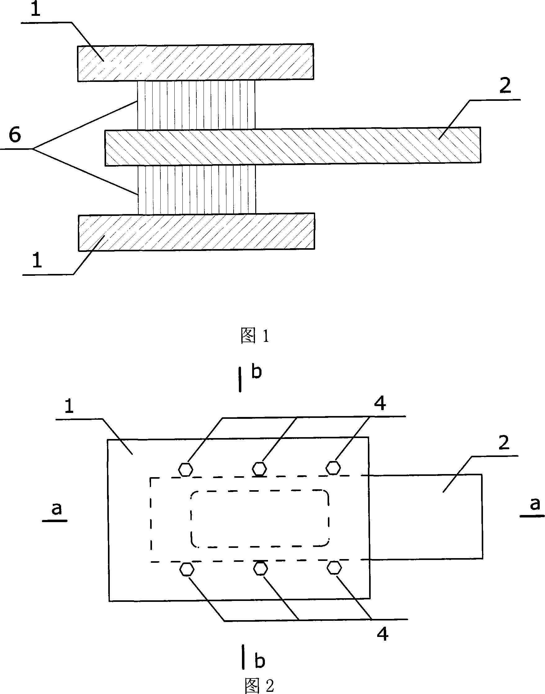
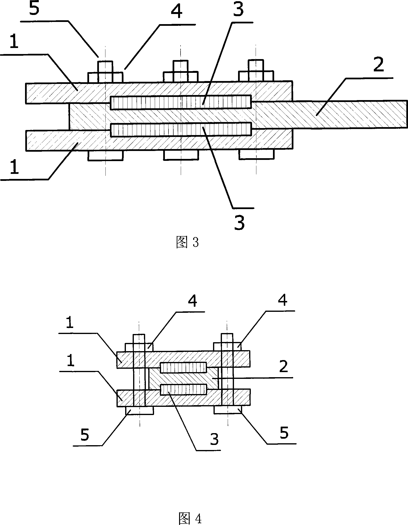
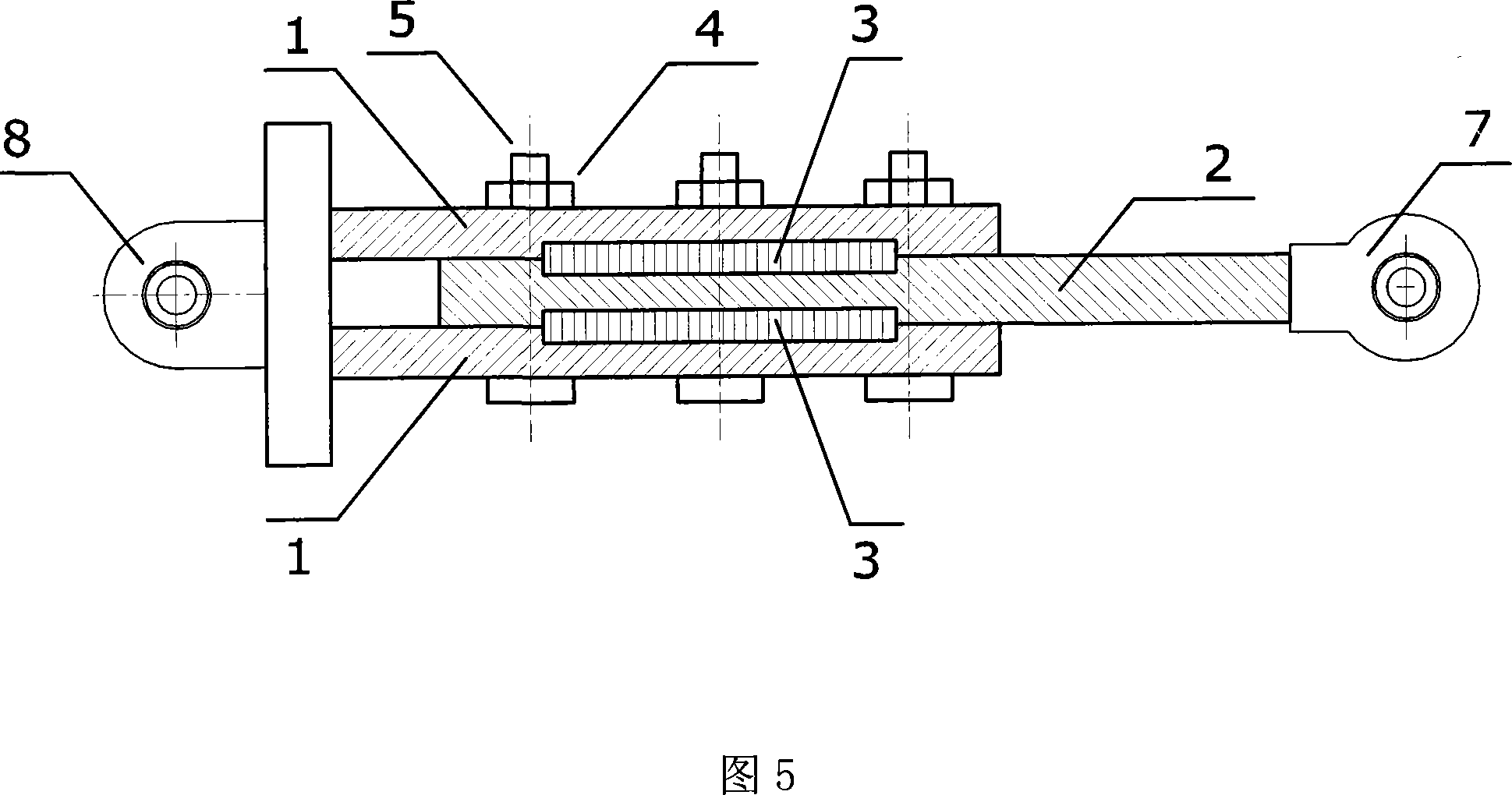
[0014] As shown in Figure 5, the shear-type lead damper includes two upper and lower cover plates 1 and a sliding plate 2. The two cover plates 1 are respectively buckled on the upper and lower surfaces of the sliding plate 2. The two cover plates 1 and Each contact surface of the sliding plate 2 is provided with a groove, and the four grooves are positioned oppositely and have the same size, forming two upper and lower cavities, and the shearing lead block 3 is directly embedded in the two cavities. A number of screw rods 5 are passed through the two cover plates 1, and the screw rods 5 are locked by a lock nut 4 to fix the two cover plates 1 and the sliding plate 2 and the shearing lead block 3 sandwiched between the two cover plates 1. The two cover plates 1 and the hinged end plate 8 are welded together, and the sliding plate 2 is welded to the connecting hinge 7.

[0015] The shear...


PUM


Abstract

The invention relates to a lead shear damper used in seismic control of buildings, which comprises a upper and a lower cover plate 1, and a sliding plate 2; wherein, the two cover plates 1 are respectively covered on the upper and the lower surface of the sliding plate 2; the contact surfaces of the two cover plates 1 and the sliding plate 2 are respectively provided with a groove, and the four grooves have opposite position, same size, and form a upper and a lower cavity in which the shear lead 3 is embedded directly. A plurality of screws 5 pass through the two cover plates 1, and the screws 5 are locked by a plurality of locknut 4 to fix the two cover plates 1, the sliding plate 2 between the two cover plates 1, and the shear lead 3. The lead shear damper used in seismic control of buildings has the advantages of simplifying the shear lead cylinder of the prior art into a shear lead block, simplifying the connection of the lead block and the cover plate since the shear lead embedded directly in the groove of the cover plate and the sliding plate, having simple structure, processing conveniently, reducing manufacturing cost, keeping the hysteretic performance, and having high application value.

Description

Technical field [0001] The invention relates to a shear type lead damper, which can be applied to the damping control of a building structure. Background technique [0002] Lead damper is a kind of control device that uses lead plastic deformation to dissipate vibration energy. The conventional shear lead damper is shown in Figure 1. This type of damper includes two upper and lower cover plates 1, a sliding plate 2, and a shear lead column 6. The main disadvantage of the conventional shearing lead damper shown in Fig. 1 is that it is difficult to connect the shearing lead column 6 and the two cover plates 1, and it consumes too much man-hour and lead material during processing. Summary of the invention [0003] The purpose of the present invention is to solve the connection problem between the shear lead column 6 and the two cover plates 1 in the existing shear lead damper, and to provide a shear type lead damper with a simpler connection. [0004] In order to achieve the above ...

Claims


Application Information

Patent Timeline
IPC IPC(8): E04B1/98
Inventor 彭凌云闫维明姚德康
Owner BEIJING UNIV OF TECH
Why Eureka
Try Eureka