
Fabricated steel bridge and installation method thereof

A prefabricated and bridge technology, which is applied in the direction of erecting/assembling bridges, bridges, bridge construction, etc., can solve the problems of potential safety hazards, shifting and falling of bolt and nut bridge decks, etc., so as to improve the bearing capacity, facilitate connection, The effect of improving stability

Inactive Publication Date: 2018-08-03
NANTONG CHENGXIN MUNICIPAL ENG CO LTD
View PDF5 Cites 9 Cited by
  • Summary
  • Abstract
  • Description
  • Claims
  • Application Information

AI Technical Summary

Problems solved by technology

[0004] However, the following problems still exist: in the existing prefabricated steel bridge, the bridge deck is only fixed on the crossbeam by bolts and nuts, and when the vehicle passes through the steel bridge, the bridge will vibrate greatly, and the vibration will cause the bolts and nuts to be connected to each other. After the nut is loose, it is easy to cause the bridge deck to shift or fall from the bridge, which poses a great safety hazard

Method used


Image

  • Fabricated steel bridge and installation method thereof
  • Fabricated steel bridge and installation method thereof
  • Fabricated steel bridge and installation method thereof

Examples


Embodiment Construction

[0046] The present invention will be described in further detail below in conjunction with the accompanying drawings.

[0047] This specific embodiment is only an explanation of the present invention, and it is not a limitation of the present invention. Those skilled in the art can make modifications to this embodiment without creative contribution as required after reading this specification, but as long as they are within the rights of the present invention All claims are protected by patent law.

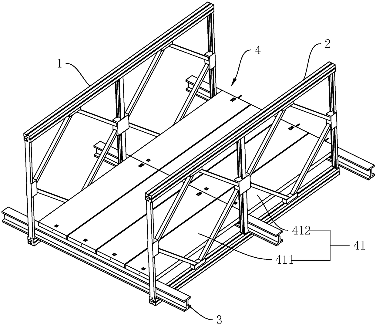
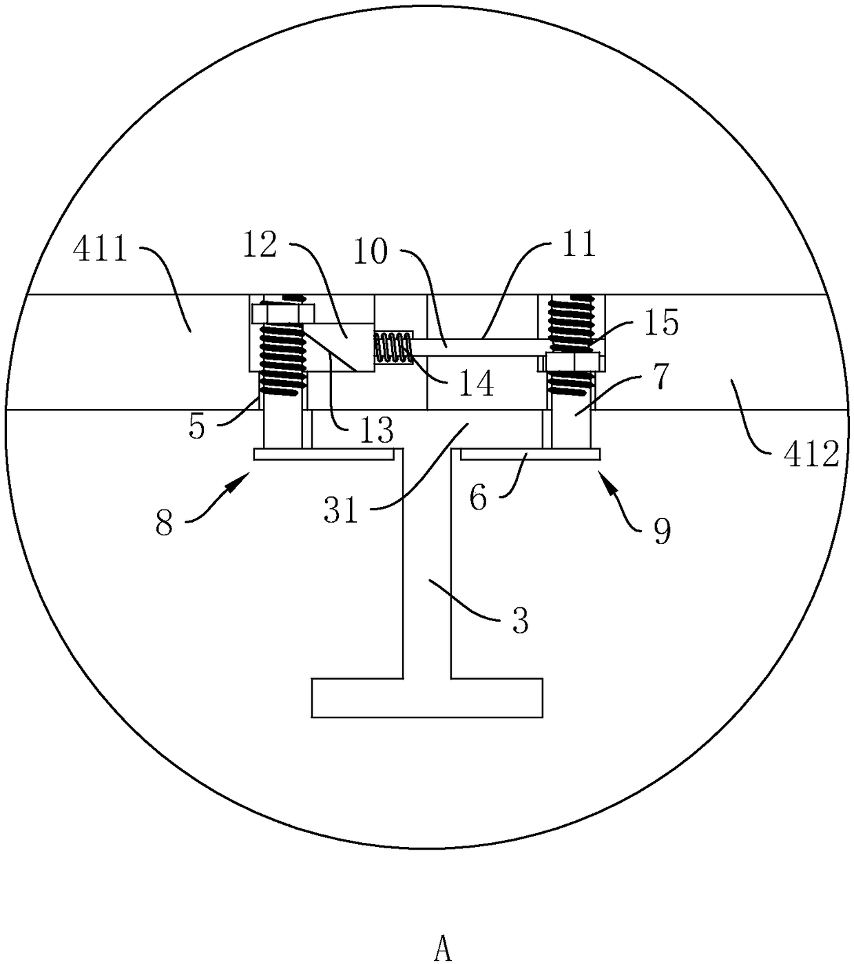
[0048] A prefabricated steel bridge, such as figure 1 As shown, it includes a left truss 1, a right truss 2 and a crossbeam 3 arranged between the left truss 1 and the right truss 2, the crossbeam 3 is I-beam; the bridge slab 4 is laid on the crossbeam 3, and the bridge slab 4 includes 4 rows of edge The bridge deck 41 arranged in the bridge width direction, the bridge deck 41 includes the first sub-board 411 and the second sub-board 412 arranged in sequence along the bridge length...


PUM


Abstract

The invention relates to the technical field of bridge construction and discloses a fabricated steel bridge. The fabricated steel bridge comprises a left truss, a right truss and cross beams, whereinthe cross beams are paved with bridge plates, and the bridge plates comprise first sub-plates and second sub-plates which are sequentially arranged in the length direction of the bridge; first bolts are arranged on the ends, close to the second sub-plates, of the first sub-plates, and second bolts are arranged on the ends, close to the first sub-plates, of the second sub-plates; each first sub-plate is slidingly connected with an insert in the length direction of the bridge, an insertion hole for the insert to be inserted is formed in each second sub-plate, each insert is provided with a wedgeblock positioned in the corresponding first sub-plate, the lower side of each wedge block is provided with an inclined plane inclined downward toward the direction of the corresponding insertion hole, the side, far away from the second bolt, of each wedge block abuts against the first bolt, and a nut matched with each first bolt abuts against the upper side of the corresponding wedge block. The sub-plates are connected, so that the sub-plates form a whole to prevent the sub-plates from shifting or falling off after the connection between the sub-plates and the cross beams is loosened or fallsoff, thus reducing potential safety hazards.

Description

technical field [0001] The invention relates to the technical field of bridge construction, more specifically, it relates to an assembled steel bridge and an installation method thereof. Background technique [0002] Prefabricated steel bridges are usually suitable for emergency emergencies. Therefore, the bridge structure is required to be light, strong in mobility, convenient in transportation, fast in assembly, and strong in adaptability. It can be widely used in wartime repairs and peacetime flood control and disaster relief. Rapid construction of road bridges and temporary road bridges, as well as auxiliary equipment for road construction. [0003] The Chinese patent with the patent announcement number CN203625760U discloses a large-span assembled highway steel truss bridge, which includes a left truss and a right truss, a crossbeam is arranged between the left truss and the right truss, and a crossbeam is arranged between two adjacent crossbeams. Wind-resistant tie ro...

Claims


Application Information

Patent Timeline
IPC IPC(8): E01D15/133E01D21/00
CPCE01D15/133E01D21/00
Inventor 卢红强刘正海张威
Owner NANTONG CHENGXIN MUNICIPAL ENG CO LTD
Learn More