Crimping apparatus
A technology for crimping equipment and crimping sheets, applied in the direction of connection, electrical components, circuits, etc., can solve the problems of negative effects on mechanical properties or electrical properties, easy surface wear, and difficulty in maintaining the surface state, so as to improve mechanical properties and electrical properties. performance effect
- Summary
- Abstract
- Description
- Claims
- Application Information
AI Technical Summary
Problems solved by technology
Method used
Image

Examples
no. 1 example
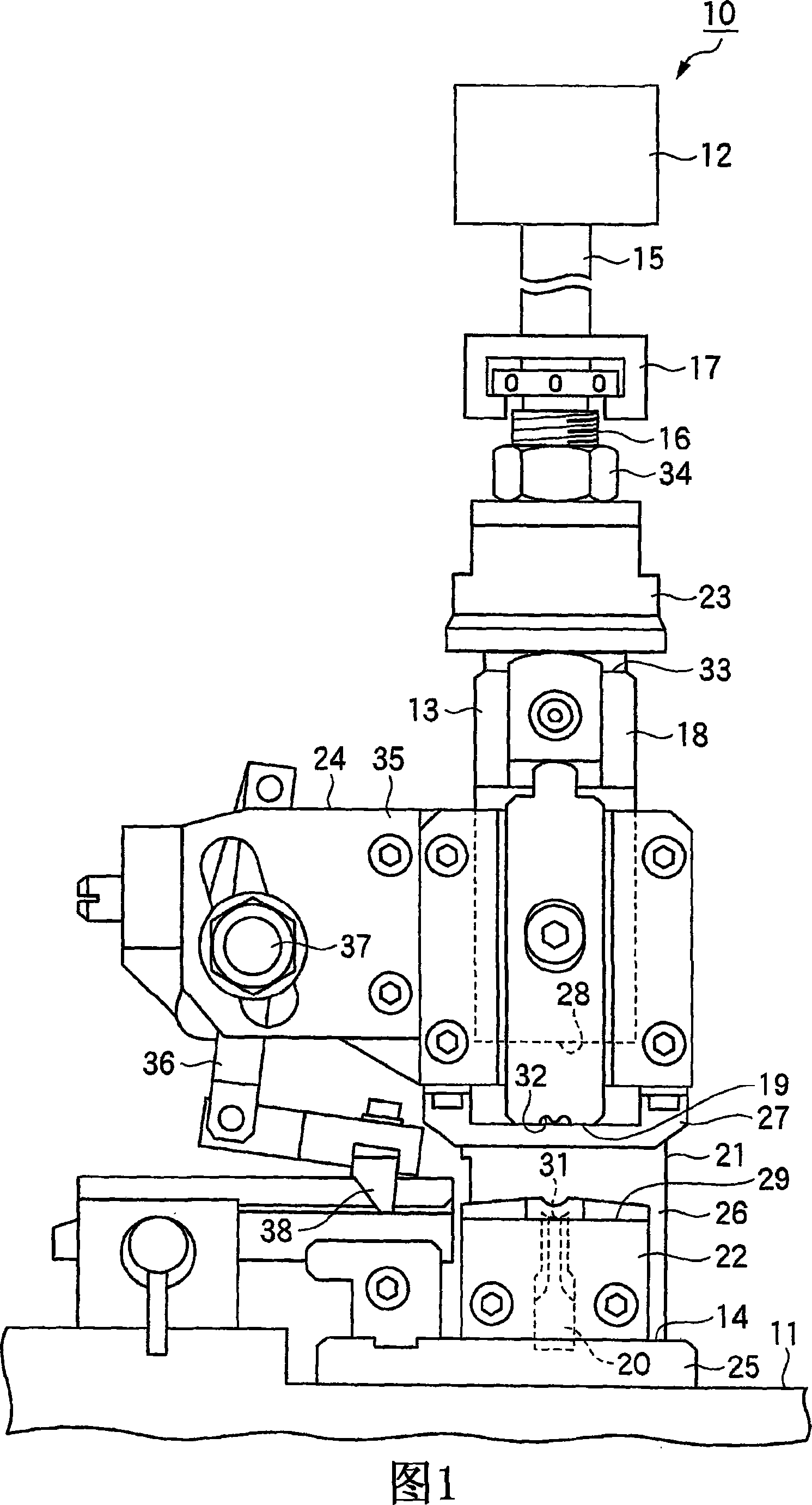
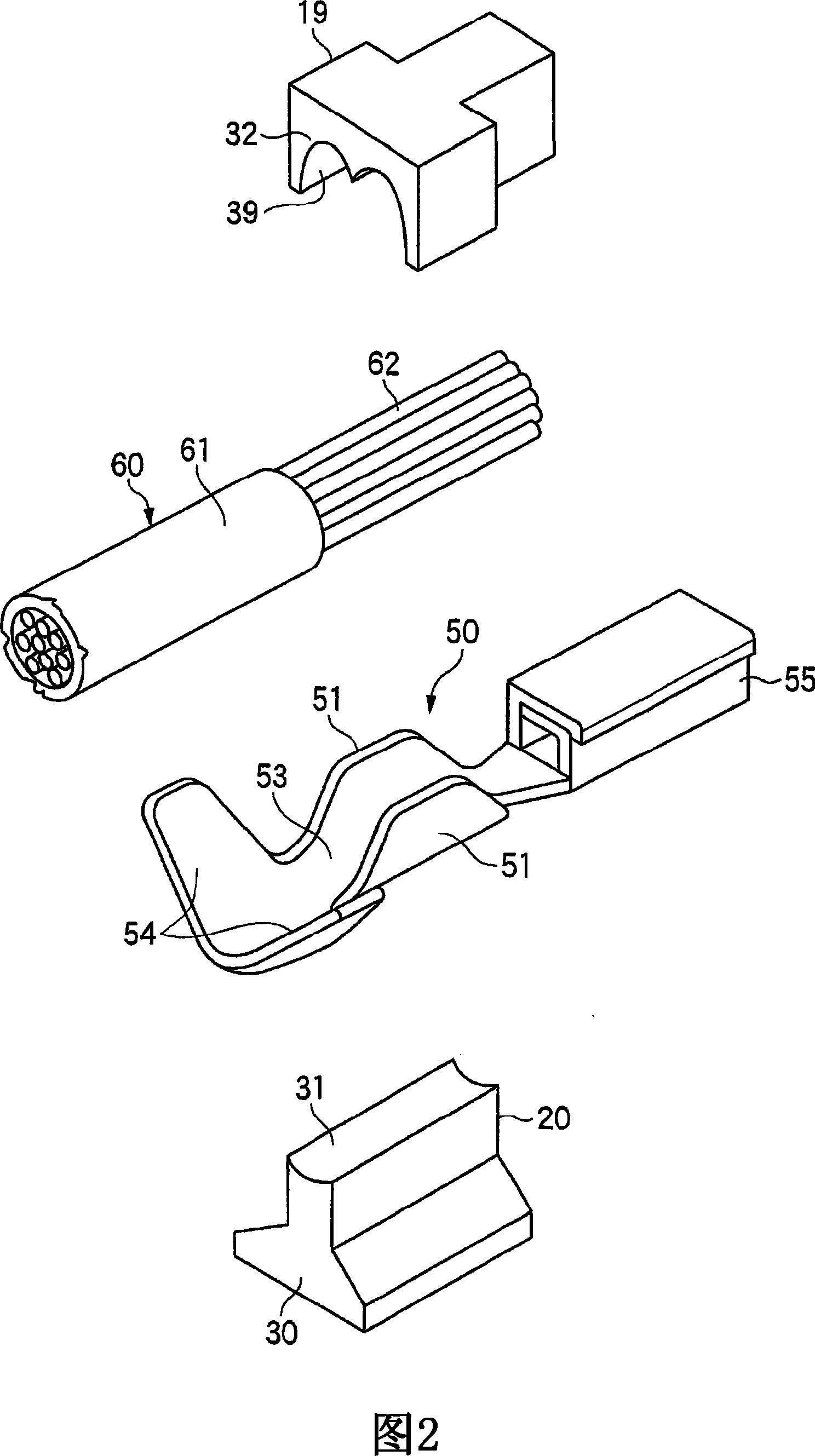
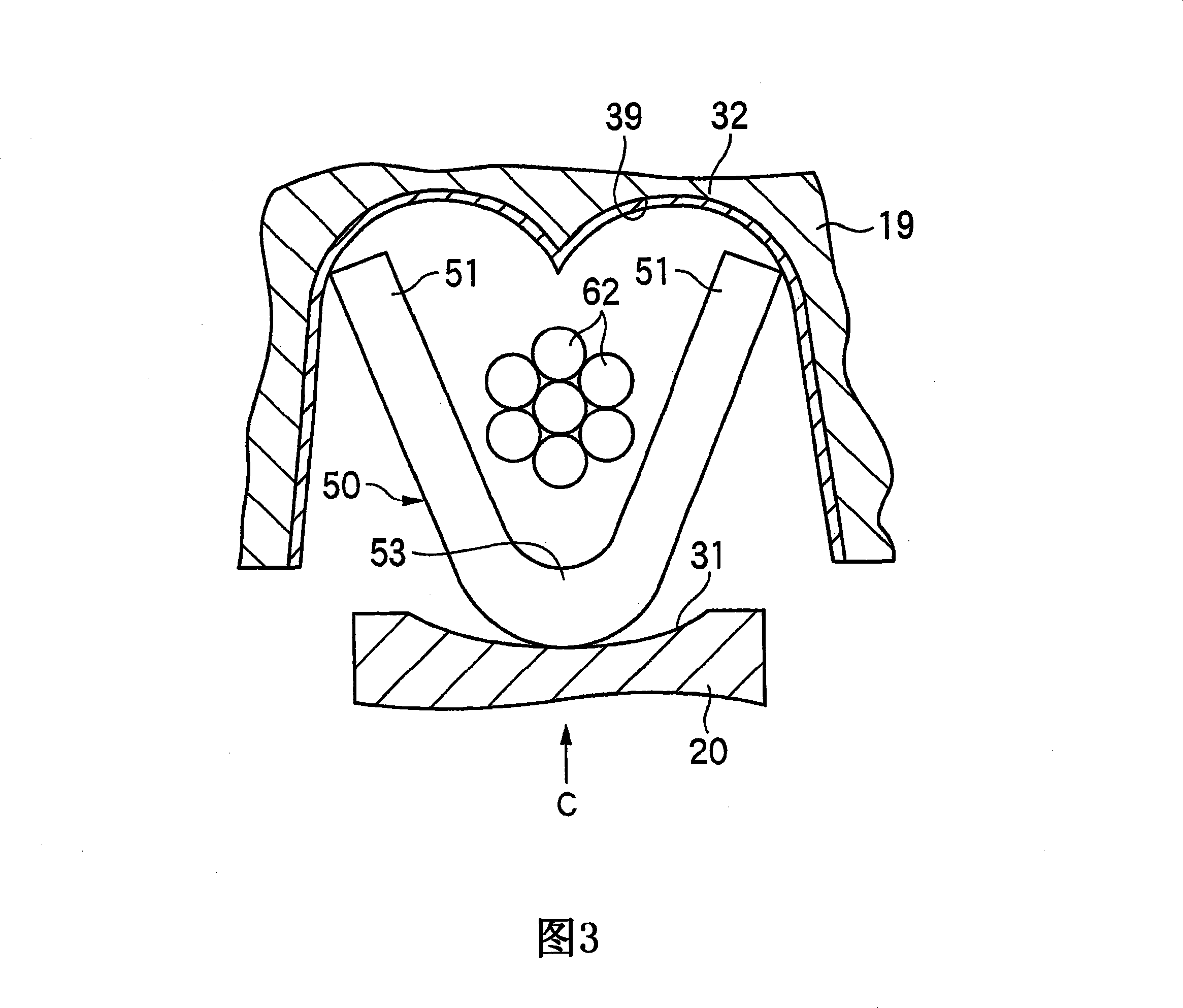
[0036] 1 to 3 show a first embodiment of the crimping device and metal terminals of the present invention, and Fig. 1 is a front elevational view of the crimping device of the first embodiment, and Fig. 2 is a crimping device shown in Fig. 1 The perspective view of the metal terminal, the crimping device and the anvil used in the equipment, Fig. 3 is an enlarged cross-sectional view of important parts of the crimping equipment of Fig. 1, Fig. 4 is when viewed from the direction C of Fig. The magnified view of the crimper in use state, Fig. 5 is an magnified view showing the surface of the compression fixing part of the mirror finish of Fig. 4 , and Fig. 6 is a view showing Fig. 5 in its used state An enlarged view of the surface of the compression-fixed part.
[0037] As shown in FIGS. 1 to 2 , the crimping device 10 of this first embodiment includes a base 11 provided on the ground or the like, a driving source 12 , and a crimping device for crimping and grounding a metal ter...
no. 2 example
[0068] Next, a second embodiment of the crimping apparatus of the present invention will be described with reference to FIG. 7 . Fig. 7 is an enlarged sectional view of an essential part of a crimping apparatus of a second embodiment. In the following embodiments, constituent elements that are functionally the same as or similar to those of the first embodiment will be given the same or similar reference numerals, respectively, and descriptions thereof will be simplified or omitted.
[0069] In the crimping apparatus 10 of the second embodiment, as shown in FIG. The hard chrome coating 41 has a hardness of Hv 850 to 1000 or more, and has a thickness of 3 to 5 μm. This hard chrome coating 41 has high hardness and is therefore excellent in wear resistance and durability.
[0070] When the crimper 19 moves downward toward the anvil 20 , the hard chrome coating 41 formed on the compression fixing portion 32 of the crimper 19 and the pair of core wire crimping piece portions of t...
no. 3 example
[0073] Next, a third embodiment of the crimping apparatus of the present invention will be described with reference to FIG. 8 . Fig. 8 is an enlarged sectional view of an important part of a crimping apparatus of a third embodiment.
[0074] In the crimping apparatus 10 of the third embodiment, a mirror-finished portion 42 having a surface roughness of not more than 0.1 μm is formed on the surface of the armor crimping fixing portion 32a of the crimper 19, and as shown in FIG. 8 , a hard chrome coating 43 is also formed on the mirror-finished portion 42 . The hard chrome coating 43 has a hardness of Hv 850 to 1000 or more, and has a thickness of 3 to 5 μm.
[0075] When the crimper 19 moves downward toward the anvil 20, the hard chrome layer 43 formed on the mirror-finished portion 42 on the armored pressing fixing portion 32a of the crimper 19 and the metal terminal 50 are The pair of armor crimping piece portions 54 are bump-engaged so as to achieve crimping with a small f...
PUM
| Property | Measurement | Unit |
|---|---|---|
| thickness | aaaaa | aaaaa |
| surface roughness | aaaaa | aaaaa |
| hardness | aaaaa | aaaaa |
Abstract
Description
Claims
Application Information
 - R&D
- Intellectual Property
- Life Sciences
- Materials
- Tech Scout
- Unparalleled Data Quality
- Higher Quality Content
- 60% Fewer Hallucinations
Browse by: Latest US Patents, China's latest patents, Technical Efficacy Thesaurus, Application Domain, Technology Topic, Popular Technical Reports.
© 2025 PatSnap. All rights reserved.Legal|Privacy policy|Modern Slavery Act Transparency Statement|Sitemap|About US| Contact US: help@patsnap.com