

Weighted prediction video encoding
A coding source, psycho-visual technology, applied in the direction of digital video signal modification, television, image data processing, etc.
- Summary
- Abstract
- Description
- Claims
- Application Information
AI Technical Summary
Problems solved by technology
Method used
Image

Examples
Embodiment Construction
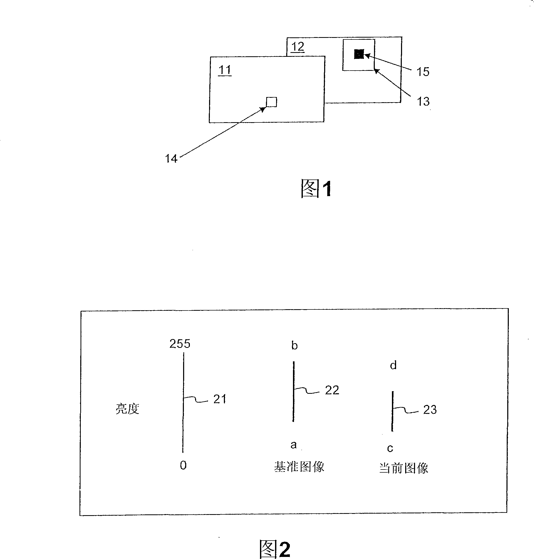
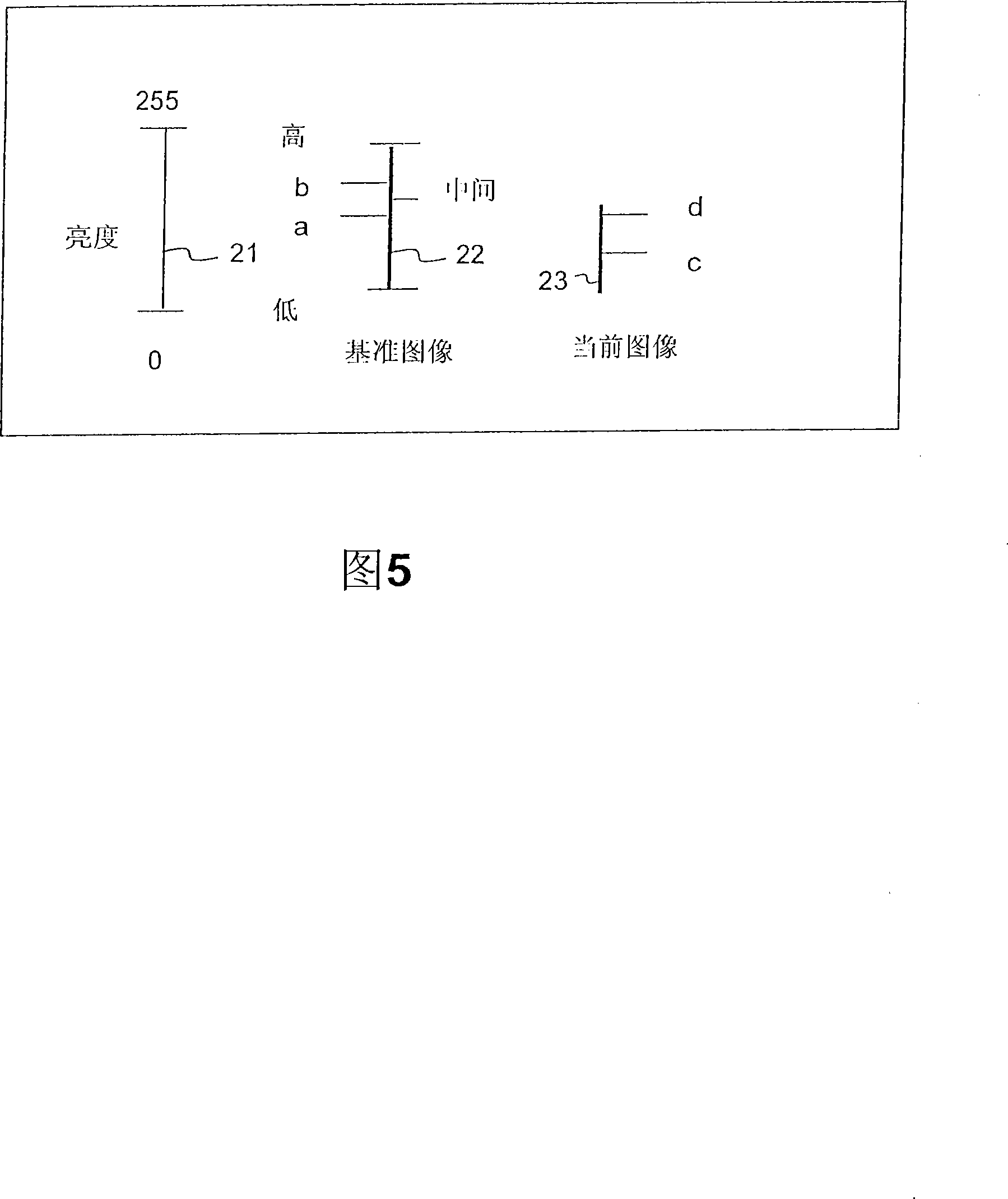
[0051] In a ramp, a sequence of images gradually increases or decreases in brightness and chrominance magnitudes, usually from 0 for black to 0, for example. Fig. 2 is a simplified example where logWD = 0 and luminance values are taken only from a P-picture example, eg the previous picture in the sequence. In Fig. 2, line 21 represents the maximum range achievable by the luminance signal in the 8-bit binary system. Line 22 represents the actual range of luminance within the reference MB of the reference image, specifically, it is between the integers a and b (a, b ε [0, 255]). Line 23 represents the actual range of MB pixel values within the current image, which is between c and d. Assume that all luminance values in the reference image are in the range [a, b], and all luminance values in the current image are in the range [c, d], and it is also assumed that the current image (Cur- pic)23 with a linear gradient towards black in brightness. In other words, a and c te...
PUM
 Abstract
Description
Claims
Application Information