Electric motor vehicle sliding automatic charging circuit

A technology for automatic charging and electric vehicles, which is applied in the direction of electric vehicles, battery circuit devices, circuit devices, etc., and can solve problems such as automatic charging circuits and devices for electric vehicles that have not yet been seen

Inactive Publication Date: 2008-07-30
方长华
View PDF1 Cites 6 Cited by
  • Summary
  • Abstract
  • Description
  • Claims
  • Application Information

AI Technical Summary

Problems solved by technology

1; There are no relevant reports about electric vehicles h

Method used


Image

  • Electric motor vehicle sliding automatic charging circuit

Examples


Embodiment 1

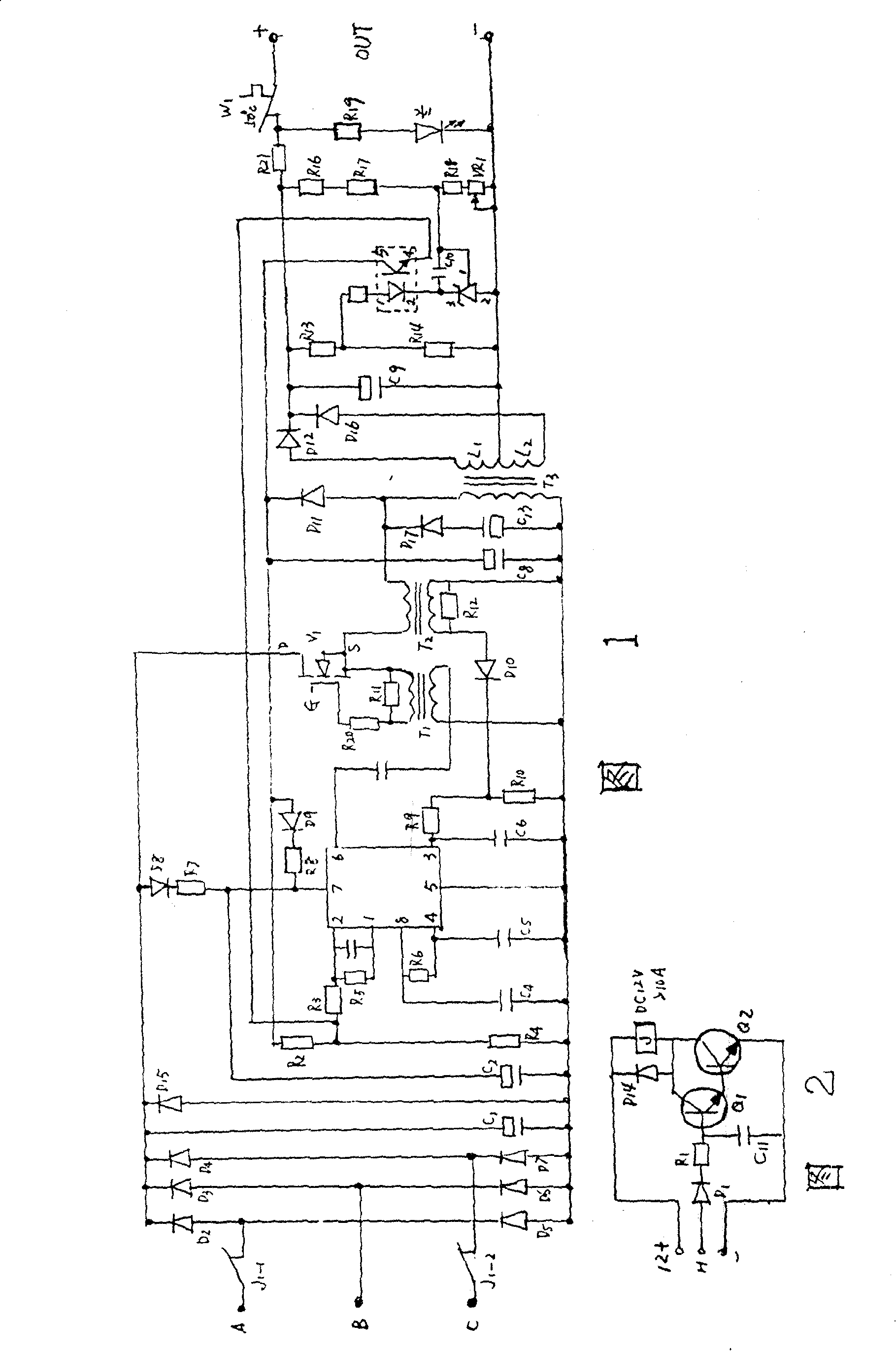
[0026] Please refer to Fig. 1 and Fig. 2, the circuit of this embodiment consists of an access and disconnection part, a power generation and rectification part, an oscillation excitation part, a voltage conversion part, a protection circuit part, a regulated output part, and a display part Composed of seven.

[0027] 1. Access and disconnection part:

[0028] access disconnected partly by the diode D 1 、D 14 , resistor R 1 , Transistor Q 1 , Q 2 , composed of relay J. The electric vehicle provides a 12V DC power supply, and the positive pole is connected to the triode Q through the pull-in wire of the relay J. 1 , Q 2 collector, the transistor Q 1 The emitter and transistor Q 2 connected to the base of the transistor Q 2 The emitter of the electric vehicle is connected to the negative pole of the 12V DC power supply, and the output terminal H of the Hall element that controls the speed of the electric vehicle running handle passes through the diode D 1 , resistor R...


PUM


Abstract

The invention discloses an electric vehicle sliding automatic charging circuit, which belongs to the device for charging the storage battery during the usage of electric vehicles. The invention provides the electric vehicle automatic charging circuit with improved circuit for executing charging in the sliding process of the electric vehicles on the basis of the invention 'electric vehicle sliding automatic charging circuit' applied by the inventor. When a single field effect transistor V1 is used for single-terminal output, the secondary electrode L1 of a high-frequency transformer T3 only outputs a half-wave rectified voltage. an S16, a D17, a C13 and an L2 are added, and the energy stored during the cut-off period T3 of the field-effect transistor V1 can be released by the D17 and the C13, so that the L2 can also output a half-wave rectified voltage in the reverse period of the V1. Accordingly, the entire device can output a full-wave rectified voltage and the rectification efficiency is improved by one time. Additionally, connected resistors and temperature-control switches can facilitate a more reliable operation of the device. The invention can prolong the running mileage of the electric vehicle, protect the controller and, more importantly, significantly prolong the service life of the storage battery.

Description

technical field [0001] The invention relates to a device for charging a storage battery during the use of an electric vehicle, in particular to an automatic charging circuit for electric vehicle sliding. Background technique [0002] With the progress of society and the development of science and technology, as well as the tension of global energy and people's continuous attention to environmental protection. The development of electric vehicles has become a demand of today's industrial production and people's lives. At present, many varieties of products such as electric vehicles and electric bicycles have come out. The power of the electric vehicle comes from the output of electric energy stored in the battery to start the mechanical movement. Therefore, the battery of the electric vehicle must maintain sufficient power to drive. Once the storage battery is out of electricity, then the electric vehicle just cannot travel, and the electric vehicle that cannot travel must c...

Claims


Application Information

Patent Timeline
IPC IPC(8): H02J7/14H02J7/32
CPCY02T10/70
Inventor 方长华
Owner 方长华
Why Eureka
Try Eureka