Safety switching unit for controlling a safety device into a safe state

A technology for switching devices and safety states, applied in safety arrangements, general control systems, components of emergency protection devices, etc., can solve problems such as contact wear of electromagnetic contactors, incorrect connection of motor protection switches and safety relays, danger, etc.

Active Publication Date: 2008-08-06
PHOENIX CONTACT GMBH & CO KG
View PDF0 Cites 15 Cited by
  • Summary
  • Abstract
  • Description
  • Claims
  • Application Information

AI Technical Summary

Problems solved by technology

[0003] The disadvantage of this safety measure is that these components have a large space requirement and a great wiring complexity
Among other things, this leads to high costs and huge maintenance
In addition, the electromagnetic contactors used exhibit contact wear
In addition, there is the dang...

Method used


Image

  • Safety switching unit for controlling a safety device into a safe state
  • Safety switching unit for controlling a safety device into a safe state
  • Safety switching unit for controlling a safety device into a safe state

Examples


Embodiment Construction

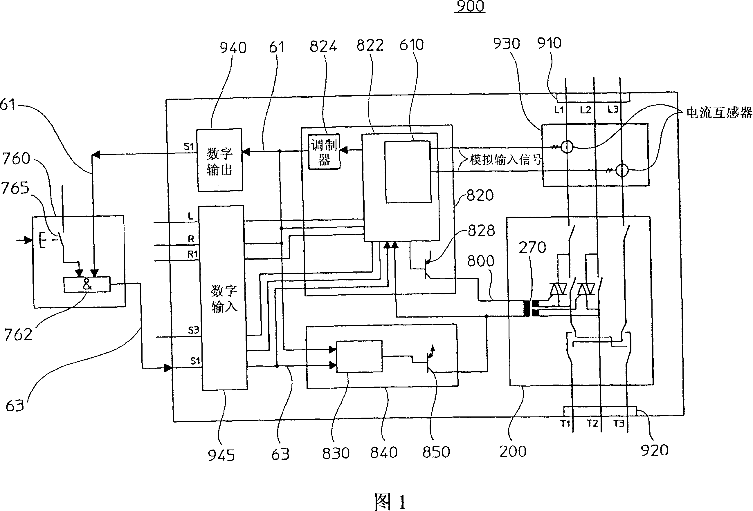
[0101] A block diagram of an exemplary safety switching device 900 is shown in FIG. 1 , the components of which are housed in a housing. The safety switching device 900 has first connection means 910 via which the safety switching device 900 can be connected to eg a three-phase power supply network (not shown). The three input lines connected to the mains network are denoted L1, L2, and L3 in FIG. 1 . Three lines L1, L2, and L3 are connected to the power amplifier 200, and the output side lines of the power amplifier are denoted by T1, T2, and T3. These three output-side lines are connected to the second connection device 920, which can connect a safety-related device such as a three-phase AC motor. It should be understood that the safety switching device 900 may be connected to multiple safety-related devices, such as single-phase or multi-phase drives. The power amplifiers used can then have a single-phase or multi-phase structure. For the sake of simplicity, the power am...


PUM


Abstract

The device has a microprocessor (822) controlling an electric drive to be protected into a safe condition during operation of an emergency switch, protective door switch and/or two-hand switch and during a faulty operation of the switching device or the electric drive. The microprocessor is implemented to determine whether a predetermined amplitude of an analog signal to be measured lies outside of a predetermined operating range. The microprocessor is a component of a safety device that is designed for multi-channel controlling of the electric drive. Independent claims are also included for the following: (1) a three phase power output stage for controlling a three phase motor (2) a reversal switching arrangement for a three phase power output stage (3) a measuring device for measuring a periodic analog signal (4) a safety-related device e.g. electric drive, comprising a measuring device (5) a method for measuring a periodic analog signal (6) a safety device for multi-channel controlling of a safety-related device.

Description

technical field [0001] The invention relates to a safety switching device by means of which a safety-related device, preferably an electric drive, can be set to a safe state. Furthermore, the invention relates to a three-phase power amplifier for driving at least one load, a measuring device for measuring periodic analog signals whose amplitudes may exceed a preset operating range, and safety for multi-channel operation of safety-related devices devices; together they are suitable for use in safety switching devices. Background technique [0002] Electric drives such as three-phase AC motors are used in applications or systems where safety-related components, safety relays, motor protection switches, or motor protection relays and fuses are essential to bring the drive into a safe state. The safety relay is used to shut down the electric drive once the emergency shutdown switch, protective door switch, or two hand switch is activated. The motor protective switch has the ta...

Claims


Application Information

Patent Timeline
IPC IPC(8): H01H47/00G05B9/03H02H1/04H02P23/00H02P1/28H01H9/54
CPCH02P1/40
Inventor 安德烈·科雷克
Owner PHOENIX CONTACT GMBH & CO KG
Why Eureka
Try Eureka