
Bulb slotting cutter

A ball-end end mill and ball-end technology, applied in milling cutters, milling machine equipment, manufacturing tools, etc., can solve problems such as different uses, different manufacturers, and large differences, and achieve smooth chip removal, precision and quality. High and wide application effect

Inactive Publication Date: 2008-08-13
GUIZHOU UNIV
View PDF0 Cites 15 Cited by
  • Summary
  • Abstract
  • Description
  • Claims
  • Application Information

AI Technical Summary

Problems solved by technology

The processing disadvantages of flat type clamping ball end mills are similar to those of integral flat rake face ball end mills; non-planar clamping ball end mills have different uses and different processing conditions. , The manufacturer is different, the difference is big

Method used


Image

  • Bulb slotting cutter
  • Bulb slotting cutter
  • Bulb slotting cutter

Examples


Embodiment 1

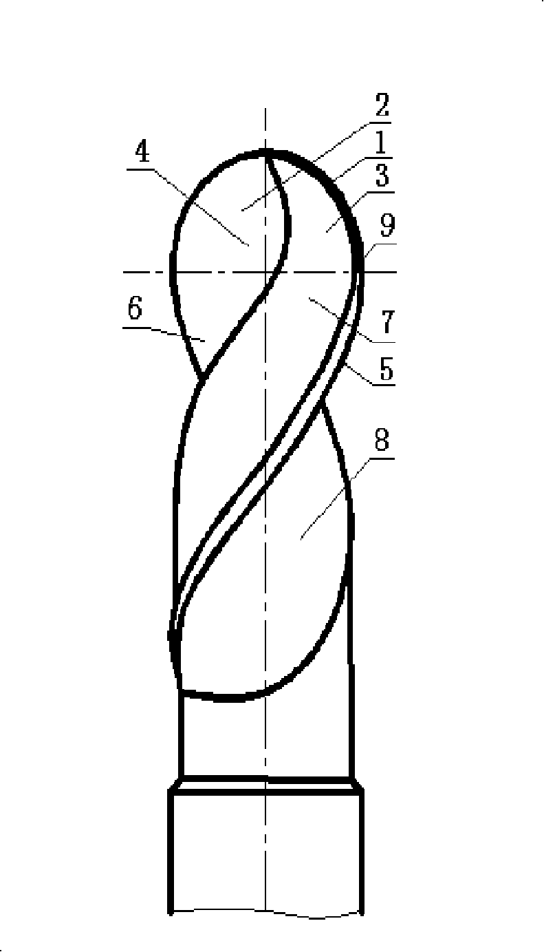
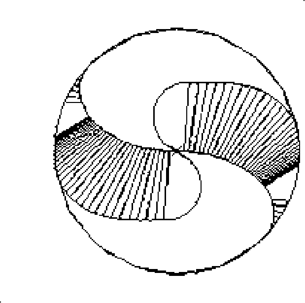
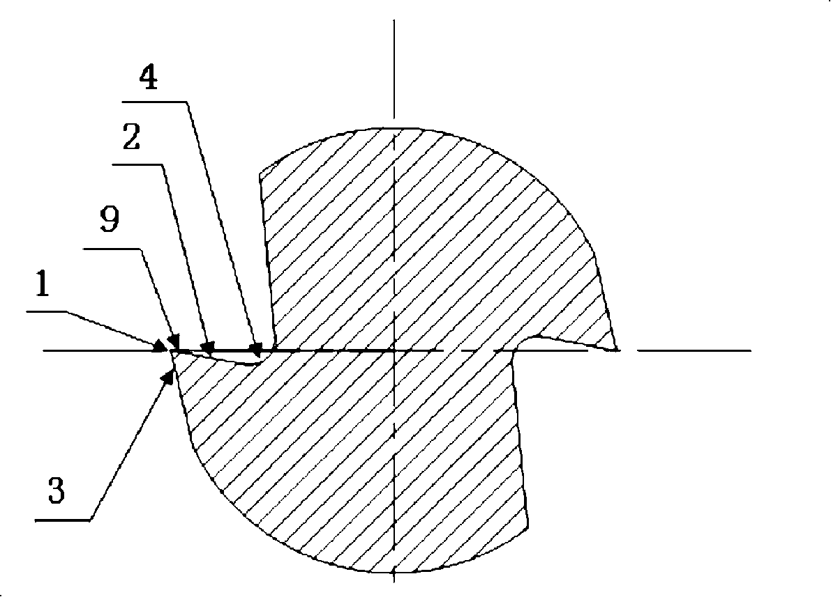
[0015] Embodiment 1 of the present invention: as attached figure 1 As shown, it includes the ball head part and the cylinder part. In the ball head part, there is an S-shaped ball edge 1 passing through the center of the ball, the ball edge rake surface 2, the ball edge flank surface 3 and the ball edge spiral groove 4; in the cylinder part, there are Spiral peripheral blade 5, peripheral blade rake face 6, peripheral blade flank 7 and peripheral blade spiral groove 8; S-shaped ball blade 1 is connected with spiral peripheral blade 5, spherical blade rake face 2 and peripheral blade rake The surface 6 is connected smoothly, the flank face 3 of the ball blade is connected with the flank face 7 of the peripheral blade, the spiral groove 4 of the ball blade is connected with the spiral groove 8 of the peripheral blade, and the rake angle of the rake face 2 of the ball blade is a positive rake angle, from inside to The outside is small in size, that is, it is smaller near the top,...

Embodiment 2

[0016] Embodiment 2 of the present invention: includes a ball head part and a conical part, and the ball head part has an S-shaped ball blade 1 passing through the center of the ball, a ball blade rake surface 2, a ball blade flank surface 3 and a ball blade helical groove 4; In the conical part, there are spiral peripheral edge 5, peripheral edge rake face 6, peripheral edge flank 7 and peripheral edge spiral groove 8; S-shaped ball edge 1 is connected with spiral peripheral edge 5, and spherical edge rake face 2 is connected with The rake face 6 of the peripheral blade is smoothly connected, the flank face 3 of the ball blade is connected with the flank face 7 of the peripheral blade, the spiral groove 4 of the ball blade is connected with the spiral groove 8 of the peripheral blade, and the rake angle of the rake face 2 of the ball blade is a positive rake angle , from the inside to the outside in a small size distribution, that is, it is smaller near the top, larger in the ...


PUM


Abstract

The invention discloses a bulb end milling cutter comprising a bulb part and a cylindrical / conical part. An S-shaped bulb edge (1) of the bulb part and a rear tool face (3) of the bulb edge connect respectively with a spiral circumferential edge (5) of the cylindrical / conical part, a front tool face (6) of the circumferential edge, and the rear tool face of the circumferential. A rather big positive front angle is provided at the front tool face (2) of the bulb edge, and a narrow edge flank (9) is provided near the cutting edge of the bulb edge front tool face; the groove bottom curve of the bulb part spiral groove (4) is a lead-variable scroll, the groove bottom curve of the spiral groove (8) of the cylindrical bulb end milling cutter the cylindrical part is a axis protecting scroll, and the groove bottom curve of the spiral groove (8) of the conical bulb end milling cutter the conical part is a conical scroll. The invented milling cutter is provided with characteristic of stable milling process and smooth chip removal, the processed products thereof have high precision and good quality, and the milling tool can be used broadly.

Description

technical field [0001] The invention relates to a milling tool, in particular to a ball-end milling cutter used for CNC machine tools. Background technique [0002] Ball end mills are a new type of tool commonly used in CNC machine tools for machining complex surfaces. They are widely used in mold manufacturing, automobile manufacturing, aerospace, electronic communication product manufacturing and other industries. There are many types of ball nose end mills popular on the market, including integral and clamping ball nose end mills. [0003] There are two main types of grinding methods for the rake face of integral ball end mills seen at present: one is to use four-axis linkage following simple grinding equipment for grinding and forming, and the ball edge is plane cutting The rake face of the ball edge is a negative rake angle or part of the negative rake angle, and the rake face of the ball edge (that is, the cutting edge of the ball head) and the peripheral edge (that i...

Claims


Application Information

Patent Timeline
Patent Type & Authority Applications(China)
IPC IPC(8): B23C5/02B23C5/10
Inventor 何林何彪赵先锋汪羿
Owner GUIZHOU UNIV
Learn More