

Bulb slotting cutter and its abrasive machining four-shaft linkage equipment
A ball-end milling cutter and grinding technology, which is applied to metal processing equipment, milling machine equipment, milling cutters, etc., can solve the problems of high production and sharpening costs of ball-end mills, high requirements for equipment manufacturing precision, and equipment design problems. Complicated and other issues, to achieve the effect of reducing installation, reducing equipment costs, and widening the use of occasions
- Summary
- Abstract
- Description
- Claims
- Application Information
AI Technical Summary
Problems solved by technology
Method used
Image

Examples
Embodiment 1
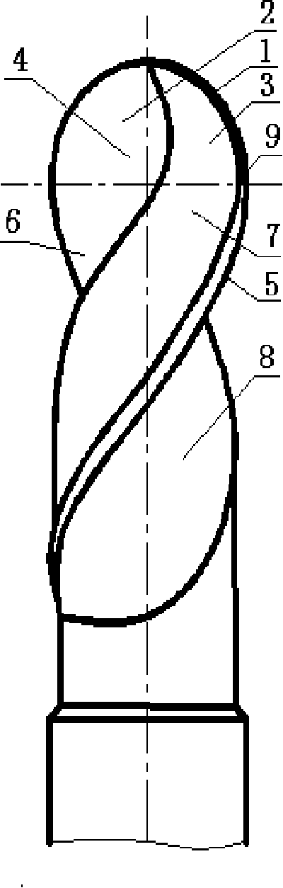
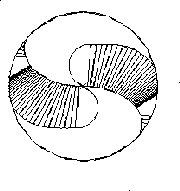
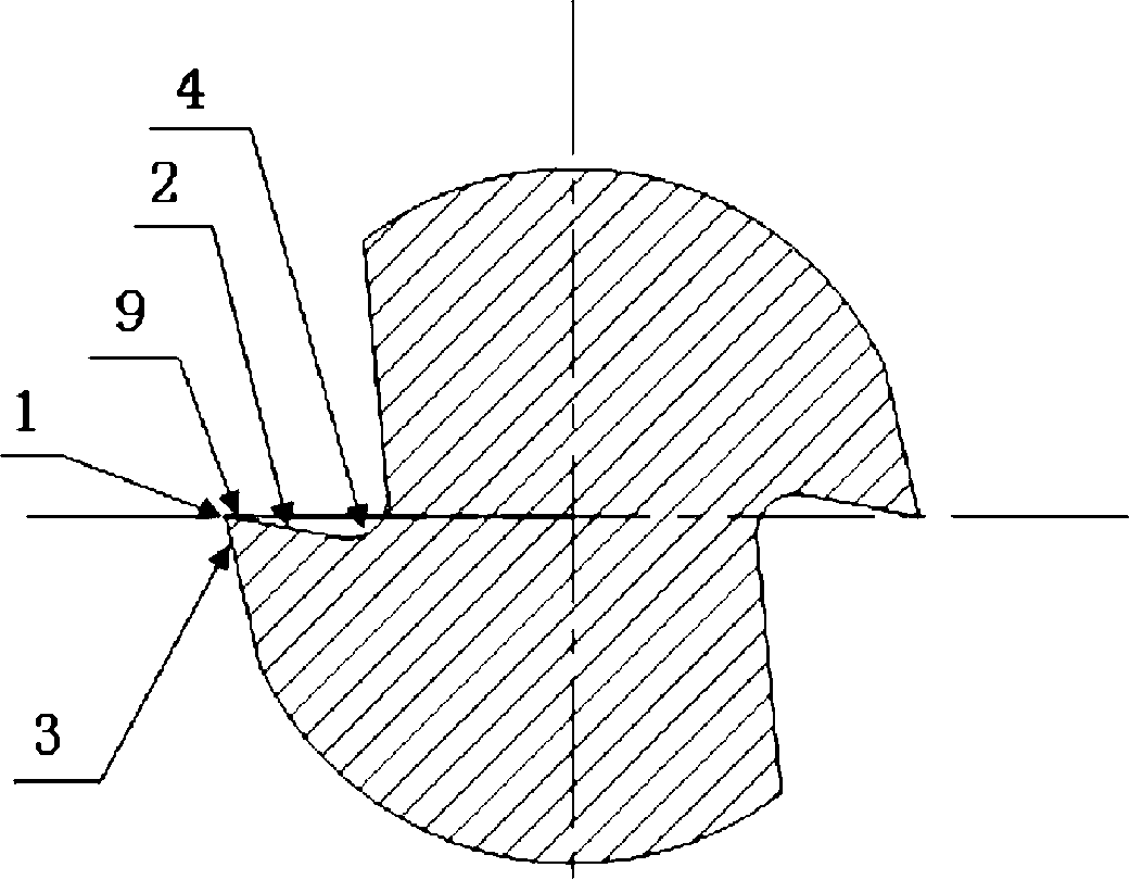
[0022] Embodiment 1 of the present invention: as attached figure 1 As shown, the composition of the ball end mill includes a ball head part and a cylindrical part. In the ball head part, there are S-shaped ball cutting edge 1 passing through the center of the ball, the ball cutting edge rake surface 2, the ball cutting edge flank surface 3 and the ball cutting edge spiral Groove 4; in the cylindrical part, there are spiral peripheral edge 5, peripheral edge rake face 6, peripheral edge flank 7 and peripheral edge spiral groove 8; S-shaped spherical edge 1 is connected with spiral peripheral edge 5, and the spherical edge rake The surface 2 is smoothly connected with the rake face 6 of the peripheral blade, the flank face 3 of the ball blade is connected with the flank face 7 of the peripheral blade, the spiral groove 4 of the ball blade is connected with the spiral groove 8 of the peripheral blade, and the rake angle of the rake face 2 of the ball blade is Large positive rake ...
Embodiment 2
[0024]Embodiment 2 of the present invention: includes a ball head part and a conical part, and the ball head part has an S-shaped ball blade 1 passing through the center of the ball, a ball blade rake surface 2, a ball blade flank surface 3 and a ball blade helical groove 4; In the conical part, there are spiral peripheral edge 5, peripheral edge rake face 6, peripheral edge flank 7 and peripheral edge spiral groove 8; S-shaped ball edge 1 is connected with spiral peripheral edge 5, and spherical edge rake face 2 is connected with The rake face 6 of the peripheral blade is smoothly connected, the flank face 3 of the ball blade is connected with the flank face 7 of the peripheral blade, the spiral groove 4 of the ball blade is connected with the spiral groove 8 of the peripheral blade, and the rake angle of the rake face 2 of the ball blade is a positive rake angle , from the inside to the outside in a small size distribution, that is, it is smaller near the top, larger in the m...
PUM
 Abstract
Description
Claims
Application Information