Flat knitting machine

A technology for knitting flat knitting machines and loom slides, which is used in knitting, weft knitting, flat knitting machines with separate action needles, etc. change, etc.

Active Publication Date: 2008-08-13
KARL MAYER STOLL R&D GMBH
View PDF2 Cites 2 Cited by
  • Summary
  • Abstract
  • Description
  • Claims
  • Application Information

AI Technical Summary

Problems solved by technology

But the control track for the slider butt cannot be changed in its width
If foreign objects, such as yarn residues or dirt, are pushed into the control track for the slider control heel, this can cause the control heel of the slider to become stuck in the control track, which can cause the control heel and / or the control track itself damage to

Method used


Image

  • Flat knitting machine
  • Flat knitting machine
  • Flat knitting machine

Examples


Embodiment Construction

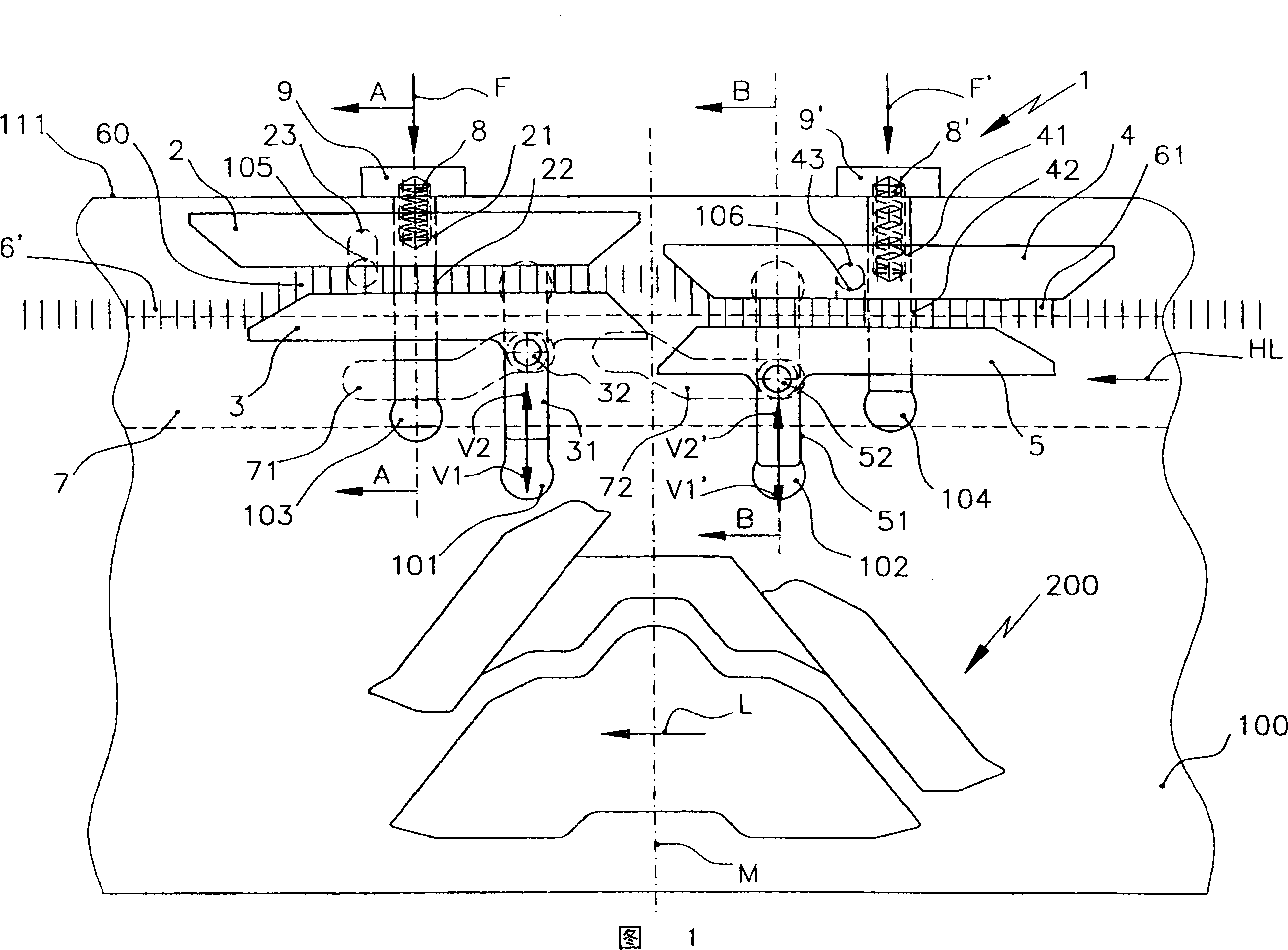
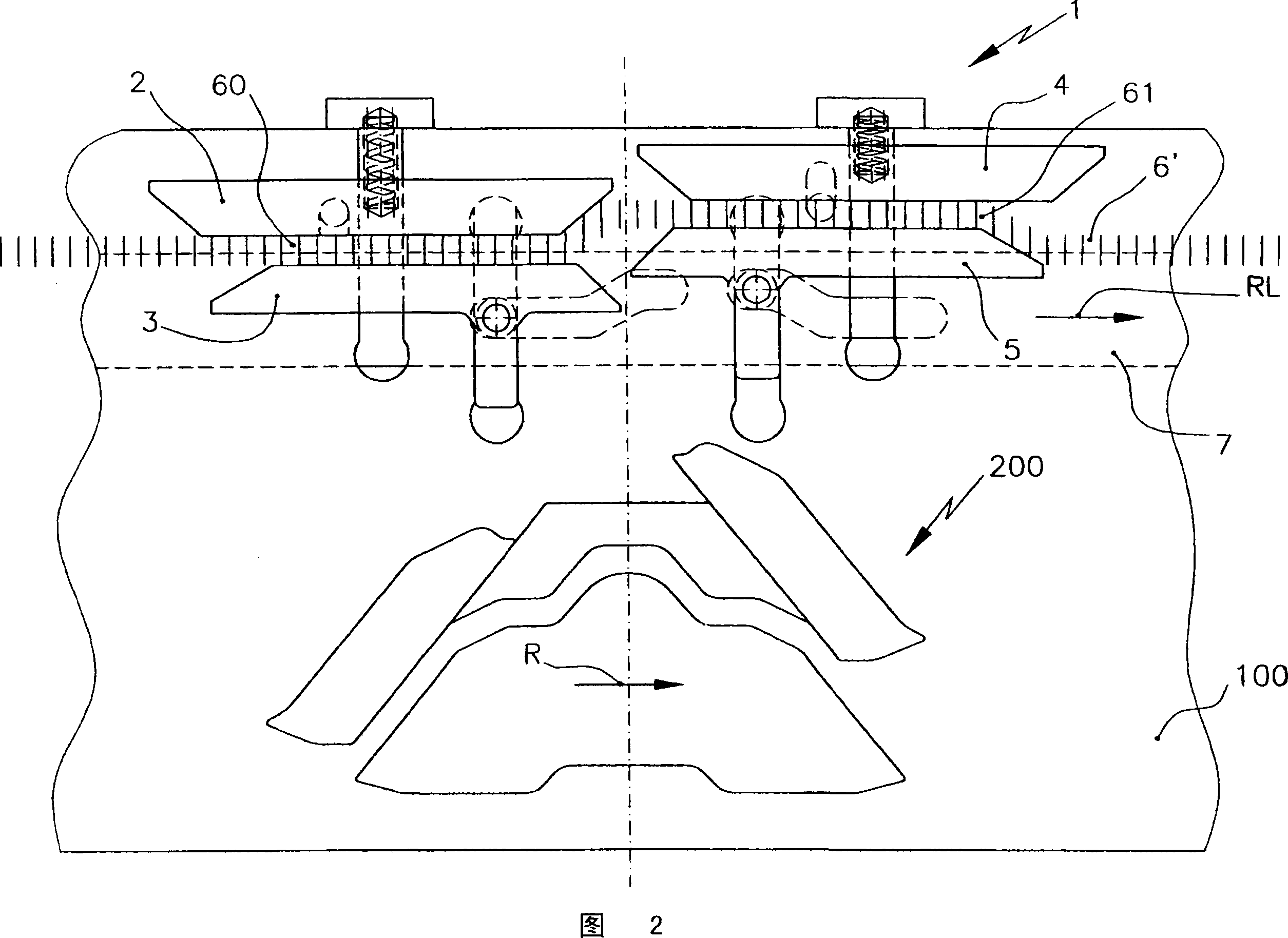
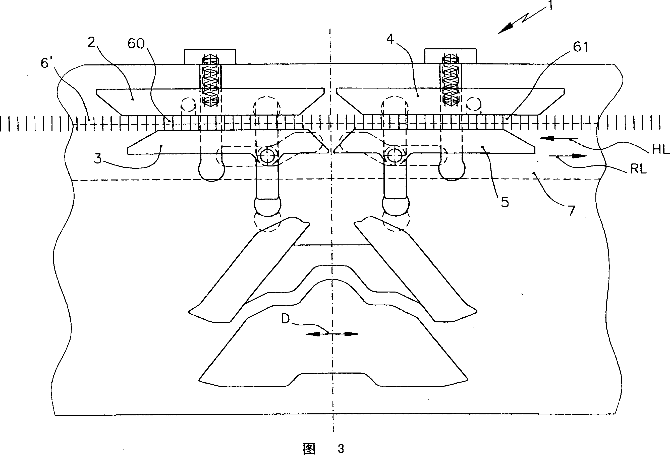
[0025] FIG. 1 shows a slider panel 1 , which is arranged on a panel base 100 above a triangular base 200 . The loom carriage, not shown, moves to the left in the direction of the arrow L in FIG. 1 , on which the panel base 100 with the panels 1 and 200 is fastened.

[0026] The slider panel 1 has a total of four panel parts 2 , 3 , 4 and 5 . In the example shown, the paneling parts 2 and 3 are arranged ahead of the central axis M of the triangular base 200 , while the paneling parts 4 and 5 are arranged behind. The panel parts 2 and 3 form the control track 60 of the control butt 6' of the slider 6 seen in detail in FIGS. 5 and 6 . Slider 6 is rotated by control rail 60 into comb slot 300 , which is likewise seen in FIGS. 5 and 6 . The panel parts 4 and 5 lagging behind the cam 200 form the control track 61 of the control butt 6 ′ of the slider, which is offset downwards compared to the control track 60 , so that the slider is again diverted from the comb gap 300 come ...


PUM


Abstract

A flat knitting machine with needles moving longitudinally in its needle bed and sliders deflectably arranged between the needles, which can be controlled by a slider panel (1) arranged on the loom slide, Wherein the slider panel (1) has a control track (60, 61) for a control butt (6') arranged on the slider (6), which consists of at least two panel parts (2, 3; 4, 5) constraints, wherein at least one paneling part (3, 5) is controllable and wherein there is a spacer (22, 5) between two paneling parts (2, 3; 4, 5) 42) and bring the two paneling parts (2, 3; 4, 5) against each other spring-loaded via the spacer (22, 42) at a minimum distance from each other.

Description

technical field [0001] The invention relates to a flat knitting machine with needles moving longitudinally in its needle bed and sliders deflectably arranged between the needles, which can pass through a slider panel arranged on the loom carriage Control, wherein the slider panel has a control track for a control heel provided on the slider, which is bounded by two panel parts, at least one of which is controllable. Background technique [0002] Such a flat knitting machine is known, for example, from EP 0 652 315 B1. The sliders of this flat knitting machine can be swiveled into or out of the comb gap by means of the slider panel. For this purpose, there is a rotatably mounted panel part which is spring-loaded in its direction of movement. This rotatable panel cooperates with a controllable panel. A control track for the control heel of the slider is formed between the two panel parts, wherein the width of the control track can be automatically adapted to the control hee...

Claims


Application Information

Patent Timeline
IPC IPC(8): D04B7/00D04B15/00D04B15/36
CPCD04B15/362D04B15/06
Inventor J・莫尔A・迪博尔德T・凯弗勒
Owner KARL MAYER STOLL R&D GMBH
Why Eureka
Try Eureka