Cam jack

a technology of cam jacks and jacks, which is applied in the direction of lifting devices, etc., can solve the problems of inconvenient and time-consuming procedures, and high cost of resources, and achieve the effects of safe and secure lifting of heavy equipment, convenient, light-weight and effectiv

Inactive Publication Date: 2008-10-16
BELLE TECH
View PDF3 Cites 12 Cited by
  • Summary
  • Abstract
  • Description
  • Claims
  • Application Information

AI Technical Summary

Benefits of technology

[0004]Accordingly, it is an object of this invention to provide simple, convenient, light-weight, and effective li

Problems solved by technology

At present, there is no simple means available for raising heavy equipment off the floor when it is necessary to service the equipment.
This is almost always an inconvenient and time consuming procedure, and an expensive use of resources.
In a typical warehouse operation, these wheels can wear unevenly, and need to be replaced rather frequently.
The difficu

Method used


Image

  • Cam jack
  • Cam jack
  • Cam jack

Examples


Embodiment Construction

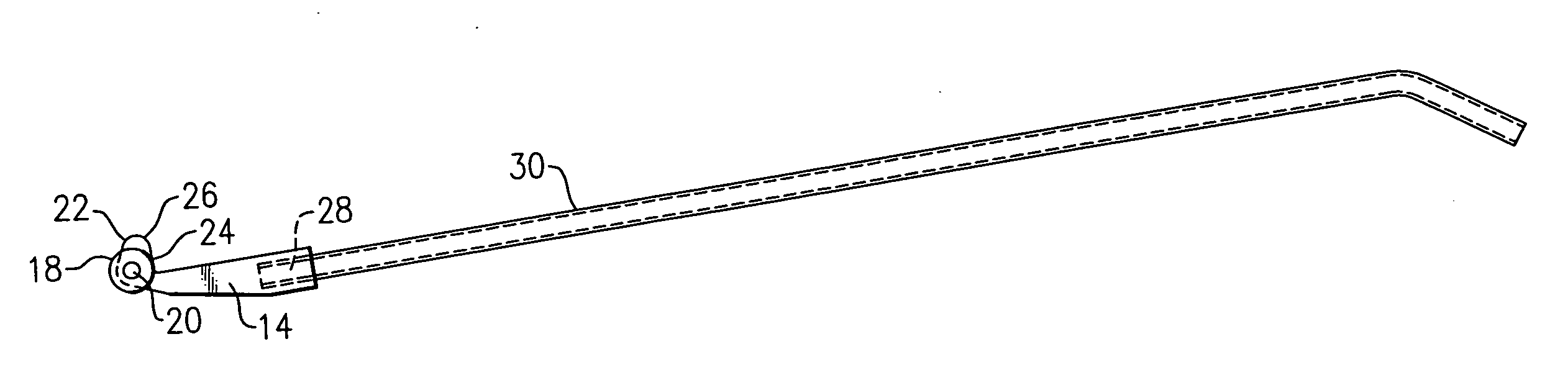
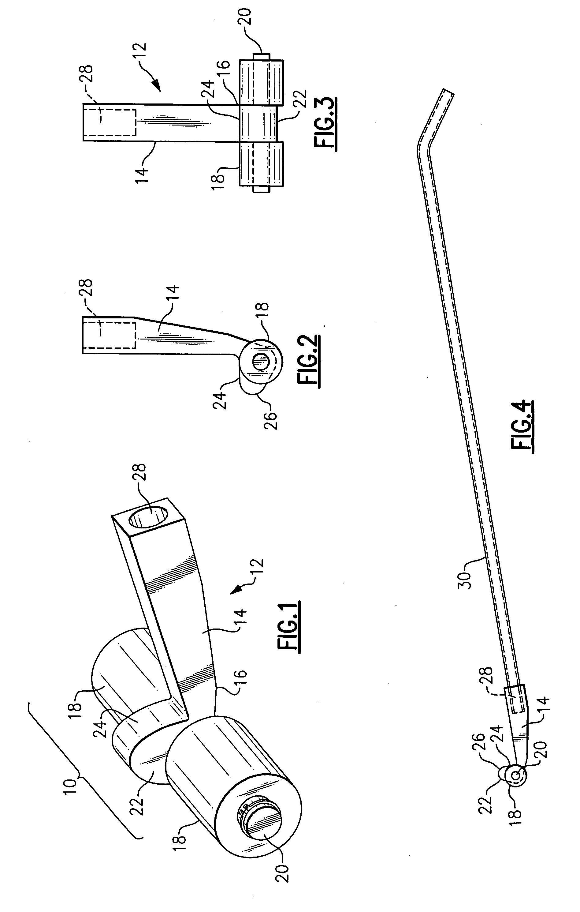
[0021]With reference to the Drawing, FIGS. 1 to 4 illustrate a cam jack 10 that employs the principles of the present invention. Here, the cam jack 10 has a unitary body portion 12 that is formed from a single piece of steel, favorably about 2-½ inches in thickness. This can be fabricated by using a water jet tool, with a garnet abrasive to cut the body portion 12 into the desired profile. By use of this technique, the device can be formed of a very hard, strong grade of steel.

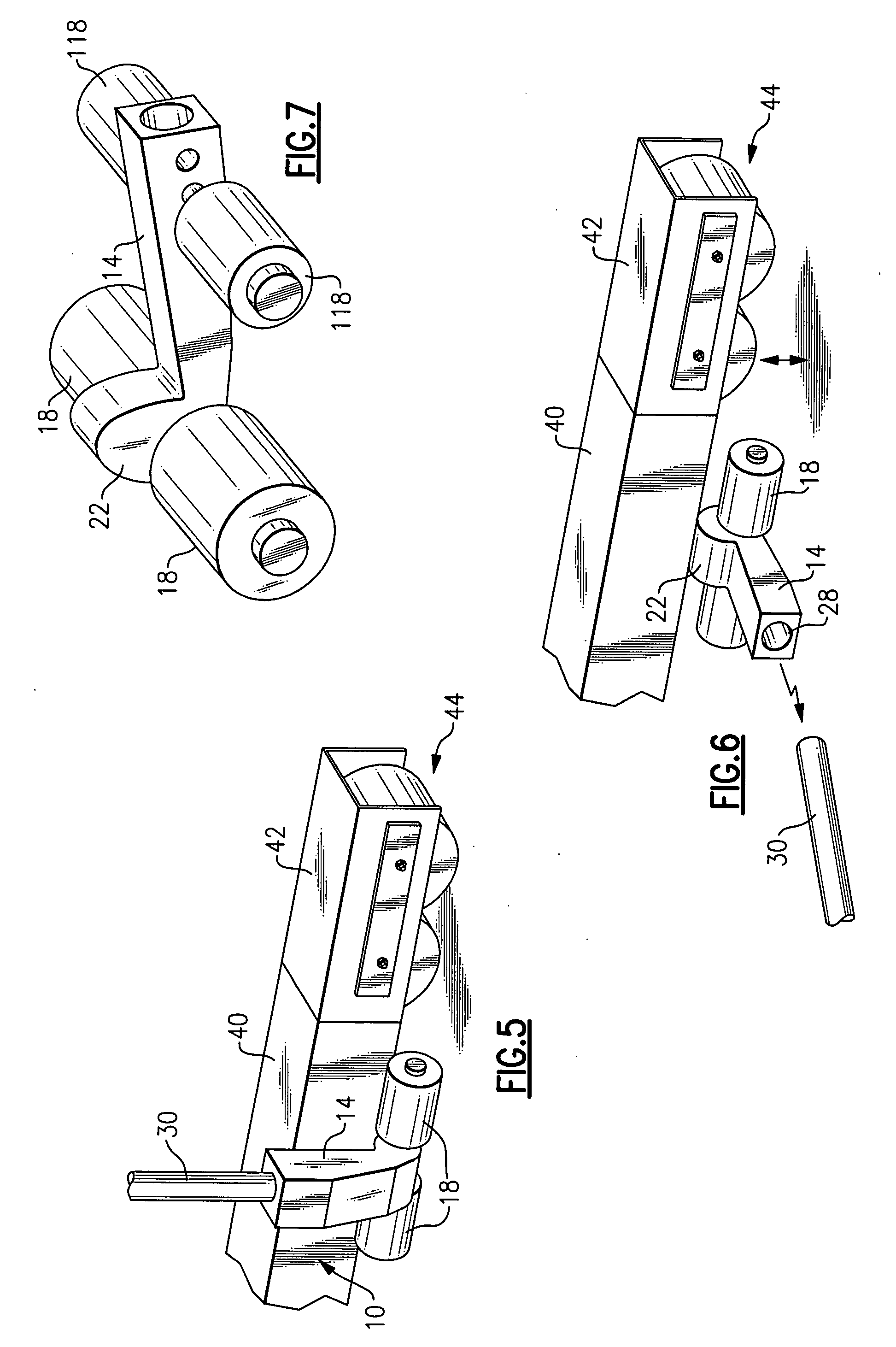
[0022]The body portion 12 is a generally L-shaped member, with a lever arm 14, and an elbow 16 formed at the distal end of the lever arm 14. There are rollers 18 mounted on an axle rod 20 that is supported in the elbow 16. A cam finger 22 projects from the elbow 16 at a nearly right angle with respect to the lever arm 14. As will be discussed later, the tip of the cam finger is angled slightly back, so that there is an over-the-center action to lock the cam jack in place in the raised position.

[0023]As can be ...


PUM


Abstract

A cam jack has an L-shaped unitary body portion, with a lever arm and a cam finger and an elbow formed between them. A pair of rollers are supported on an axle that is affixed at the elbow. A socket or fitting formed at the proximal end of the lever arm allows a lever handle to be removably attached. The cam finger is oriented at a near right angle to the lever arm. When the lever arm is disposed vertically, the cam finger can be positioned under the item to be lifted, and then as the lever arm is rocked downward as lobe tip of the cam finger urges the item upward. When the lever arm is positioned horizontally against the floor, the lobe tip is displaced outward past the axle of the rollers, so there is an over the center action holding the cam jack stable while supporting the load. An additional set of rollers can be present so the device may be used as a dolly.

Description

BACKGROUND OF THE INVENTION[0001]This invention relates to jacks or lifts for raising heavy machines or equipment, and is more particularly concerned with a hand-operated cam jack which is convenient in size and weight, and which employs simple lever action to lift a machine up off the supporting floor surface, and which can hold the same stably at an elevated position.[0002]At present, there is no simple means available for raising heavy equipment off the floor when it is necessary to service the equipment. For most types of equipment, a heavy service equipment item, such as railroad jack, or sometimes a forklift, is brought in and the forks are slid under the machine. This is almost always an inconvenient and time consuming procedure, and an expensive use of resources.[0003]One example of an application for a simple jack in a materials handling vehicle, such as a pallet transporter, which typically has groups of wheels held in place on horizontal support legs at the base of the un...

Claims


Application Information

Patent Timeline
IPC IPC(8): B66F3/00
CPCB66F3/005
Inventor SMEETON, ROBERTCSIGI, PETER
Owner BELLE TECH
Why Eureka
Try Eureka